Modular PCB Setup for Educational and Research Purposes
Modular PCB Setup for Educational and Research Purposes
About us
I'm currently an advanced undergraduate electrical engineer student in Universidad de Costa Rica in Costa Rica. I've designed some PCBs but I'm loooking forward to expand my knowledge and skills in this area. On the other hand, I'm developing this project with a professor with plenty of experience to make the PCBs for a course from the university in order to use them for educational purposes in power electronics.
About the project
The main idea of the project is to design several circuits that will form a modular PCB setup that can adapt to the needs of the application. The modularity would help to reduce connection and hardware errors when doing projects or experiments for educational or research purposes and it would help to have a more stable signal, contrary of using breadboards.
Current status of the project
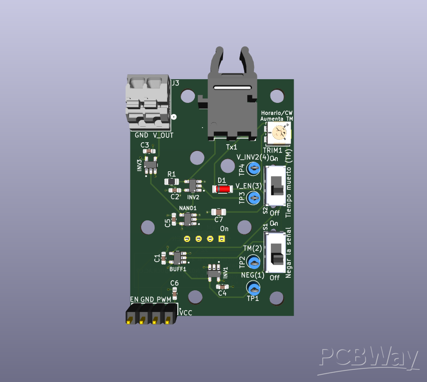
The digital to fiber optic converter is one of the modular PCBs that we want to make and for now, we have a prototype. It is meant to be used with other PCBs forming a modular PCB station using a multicontroller (LAUNCHXL-F28379D or ESP32-DEVKIT-V1) (this board is still in development). Its purpose is to receive a PWM signal from the microcontroller and convert it to a fiber optic signal. This is because we want to use it connected to a H bridge board (full bridge board PEH2015 from Imperix) that receives only fiber optic signal. The idea with the switches is that you can select if you want the PWM signal (input signal) inverted, with dead time included as protection for the H bridge circuit and also, adjust the dead time with a trimmer. Additionally, the extra holes in the PCB allows to put another PCB above to support the board with nylon pillars as well as using as input, the same PWM signal transmitted by the microcontroller. On the other hand, the output signal of the board can be the fiber optic signal or the terminal block.
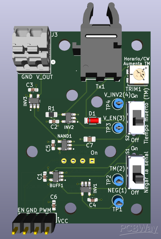
Figure 1. Front view of the PCB in 3D.
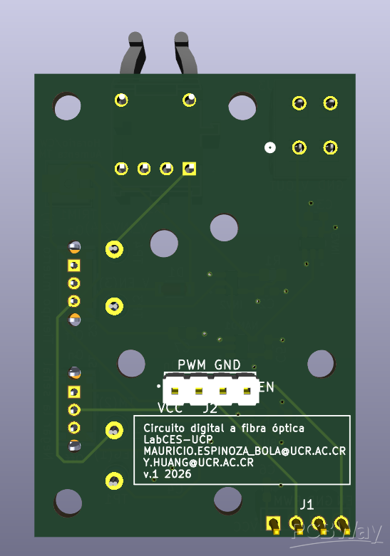
Figure 2. Back view of the PCB in 3D.
The list of materials needed to make the PCB digital to fiber optic converter and the github repository are attached to this project.
Future of the project
Due to the modularity of the project, there are several PCBs that we want to make in order to future proof it and increase its functionality to other areas and projects. There are some boards that need to be made in order to start using the modular setup for educational and research purposes. Our current priority is to design the PCB that contains the microcontroller and it needs to be made with a port that allows a direct connection with the digital to fiber optic converter board. The microcontrollers that we want to use are LAUNCHXL-F28379D and ESP32-DEVKIT-V1, the idea is that we can select which one we want to use and the board needs to be able to adapt to both of them. Finallly, all the next PCB designs are going to be develop with the aim to help teaching power electronics to electrical engineer students and also, develop new research projects in the laboratory, such as controlling systems.
Collaboration with PCBWay
Due to the project being in its early stages, we would benefit greatly with the support of PCBWay. We have seen previous PCB boards made by them and their quality and support caught our attention. This collaboration would help us in prototyping and perfecting our designs in order to use this project for teaching power electronics and doing research in the university, resulting in helping future electrical engineers and enhancing knowledge.Therefore, PCBWay's support would highly contribute to the education of multiple students and allow new research projects to develop. We are very excited and grateful for having the opportunity to apply for a sponsorship and we are looking forward for working together.
- Comments(0)
- Likes(0)