ESP32 Wi-Fi Enabled PID Self-Levelling Gimbal
ESP32 Wi-Fi Enabled PID Self-Levelling Gimbal
Project Overview
This project is an ESP32-based two-axis self-levelling gimbal designed to keep a small platform level using real-time sensor feedback and servo control.
The system uses an MPU6050 IMU to measure roll and pitch angle, two MG996R servos to correct the platform position, and a PID control loop to stabilise the platform. The ESP32 also hosts a Wi-Fi dashboard for live telemetry, manual control, reset-to-flat operation, and stabilisation mode switching.
I built this project as a personal engineering portfolio project to combine embedded systems, control systems, PCB design, CAD, 3D printing, and practical hardware integration into one complete build.
Why I Built This Project
I wanted to build something more complete than a simple breadboard circuit. The goal was to design a project that included real electronics, mechanical movement, control theory, PCB design, and physical manufacturing.
A self-levelling gimbal is useful because it connects to real engineering applications such as robotics, camera stabilisation, drones, aerospace systems, and feedback control. It also gave me a practical way to understand PID controllers, sensor fusion, servo movement, and mechanical design.
System Architecture
The gimbal works as a closed-loop control system.
The MPU6050 measures the platform movement. The ESP32 processes the sensor data, estimates the roll and pitch angles, calculates the control correction using PID, and sends updated positions to the servos. The servos then physically move the gimbal frame to reduce the angle error and keep the platform level.
The basic control loop is:
MPU6050 reads acceleration and gyroscope data.
ESP32 estimates roll and pitch.
PID controller compares the measured angle with the target angle.
Servo output is adjusted.
Platform moves closer to level.
The loop repeats continuously.
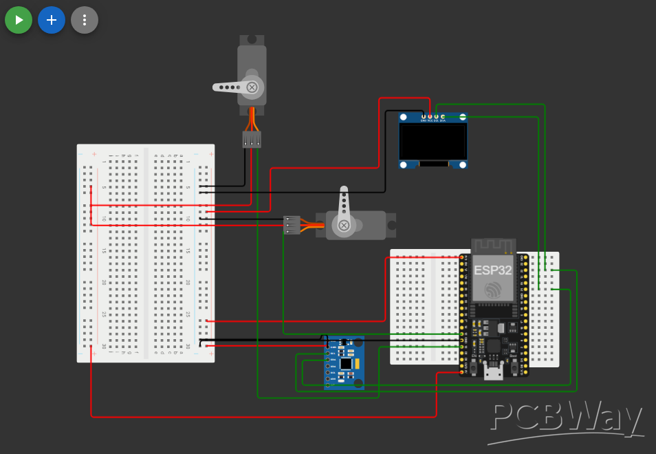
Electronics Design
The first version of the project was tested using breadboard wiring. This allowed me to check the MPU6050, servo movement, ESP32 code, Wi-Fi dashboard, and PID control before designing a permanent board.
After testing the circuit, I designed a custom 2-layer KiCad carrier PCB.
(I cant upload the breadboard picture for some reason, I apologise)
The PCB is a carrier board rather than a complex processing board. Its purpose is to make the final wiring cleaner, safer, and more reliable.
The board includes:
ESP32 header sockets
Roll servo connector
Pitch servo connector
5V power input
Bulk capacitor for servo power stability
Remote MPU6050 connector
Clear silkscreen labels
Mounting holes for the enclosure
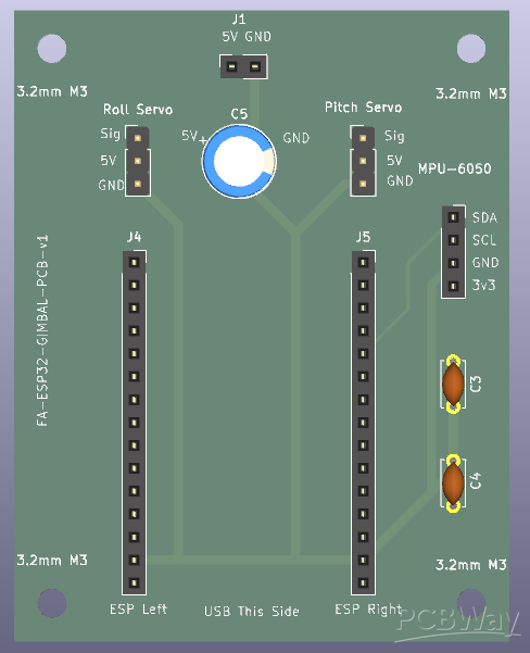
The PCB is approximately 70 mm × 55 mm and is designed to fit inside the 3D printed electronics enclosure.
PCB Design
The PCB was designed in KiCad. I completed the schematic, PCB layout, routing, design rule checks, Gerber export, and 3D board preview.
The board was designed to keep the ESP32 removable by using headers, so the development board can still be reused or replaced later. The servos and MPU6050 also connect through headers, making the system easier to assemble, test, and repair.
The main design goal was not to make the smallest PCB possible. The goal was to make a clear, practical, serviceable carrier board suitable for a student prototype.
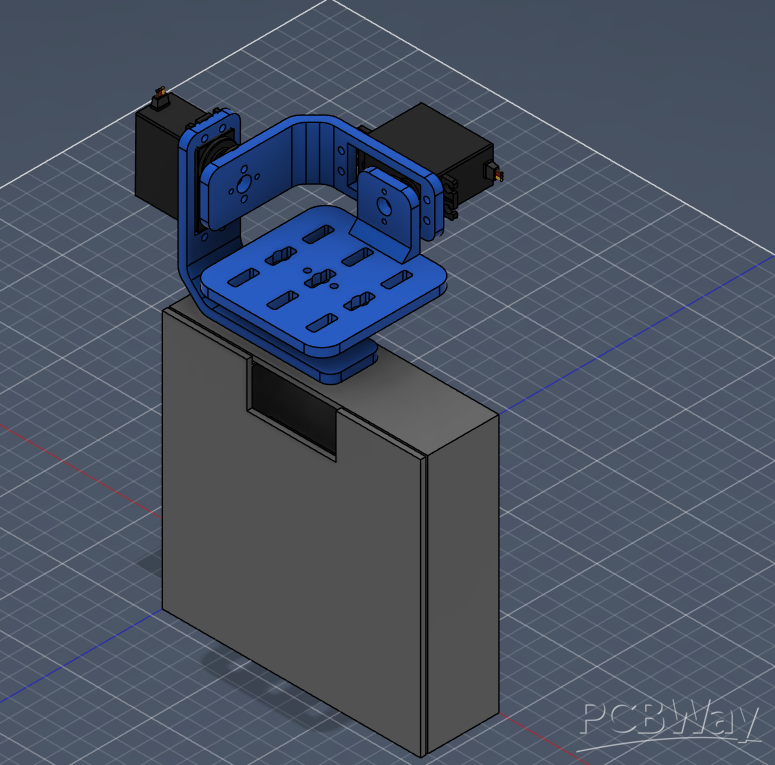
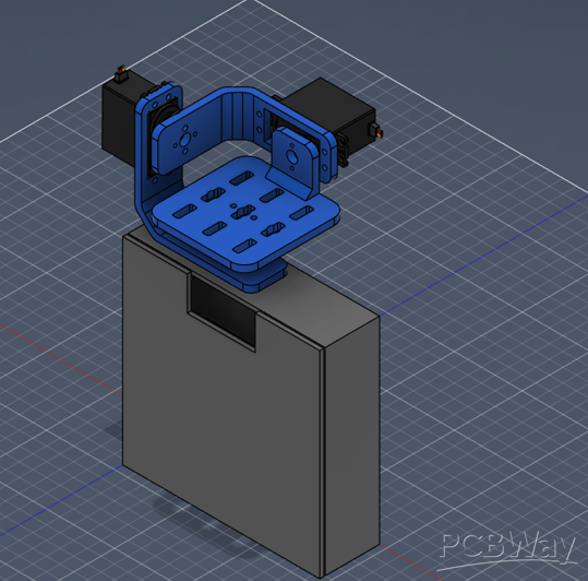
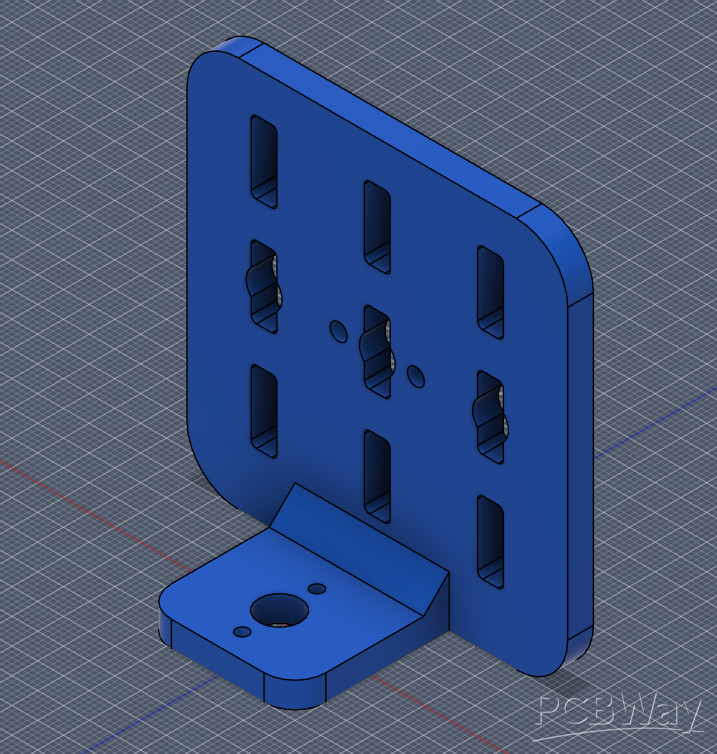
Mechanical CAD Design
The mechanical frame and enclosure were designed in Fusion 360.
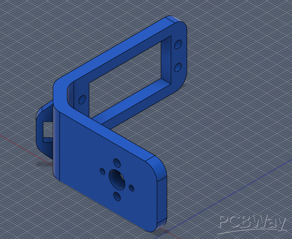
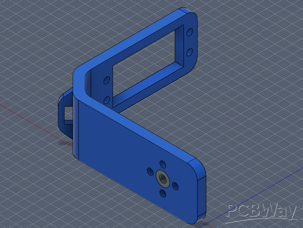
The CAD design includes:
Roll servo bracket
Base/pitch servo bracket
Stabilising platform
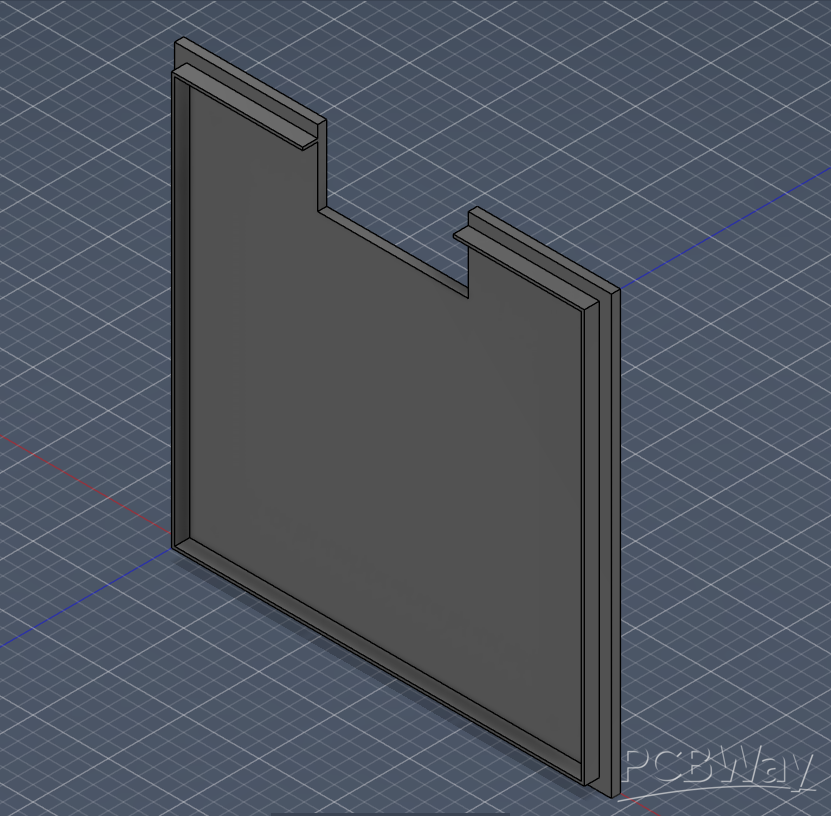
Electronics box
Removable lid
Cut outs for wiring, USB access, switch, and IMU wiring
Mounting space for the PCB and power system
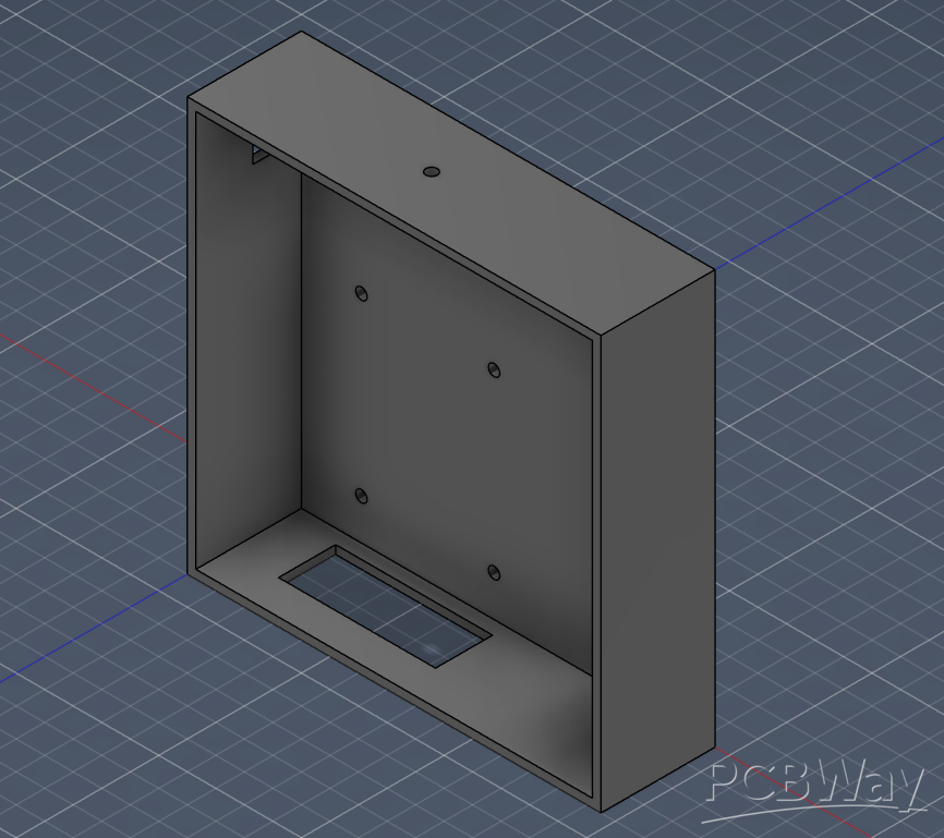
The electronics enclosure was designed to hold the PCB and power system while supporting the gimbal assembly above it. The moving platform is kept separate from the electronics box so the IMU and gimbal structure can move correctly.
Software and Control
The firmware is written for the ESP32 using C/C++.
The main software features are:
MPU6050 sensor reading
Complementary filter for roll and pitch estimation
PID control for stabilisation
Servo control for two axes
Wi-Fi dashboard
Manual control mode
Stabilisation mode
Reset-to-flat function
Heartbeat safety check
The complementary filter helps combine accelerometer and gyroscope data. The accelerometer gives a stable long-term angle estimate, while the gyroscope gives fast short-term movement data. Combining them gives a smoother and more responsive angle estimate.
The PID controller then uses the angle error to calculate how much each servo should move.
Wi-Fi Dashboard
The ESP32 hosts a local Wi-Fi dashboard that helps with testing and tuning.
The dashboard allows the user to:
View live roll and pitch angles
Switch between manual and stabilisation mode
Move the servos manually
Reset the target angle
Monitor the system during testing
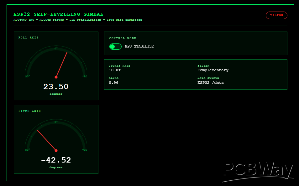
This made the project much easier to debug because the system could be tested without constantly changing the firmware.
Current Project Status
The electronics design, firmware, PID control, Wi-Fi dashboard, KiCad PCB, and Fusion 360 CAD model are complete.
The project is currently at the manufacturing stage. The next steps are:
Manufacture the PCB.
3D print the mechanical parts.
Solder the headers and connectors.
Assemble the full gimbal.
Test the power system.
Tune the PID values.
Record a final demo video.
Publish the final GitHub and portfolio documentation.
Why PCBWay Support Would Help
This is a student-funded personal engineering project. The cost of PCB fabrication, 3D printing, shipping, and VAT is significant for a small prototype.
PCBWay support would help me move the project from completed design files into a finished physical build. This would allow me to complete the final assembly, testing, and documentation.
In return, I would credit PCBWay in:
the GitHub README
my engineering portfolio page
the final LinkedIn project post
the project documentation
The final documentation will include PCB screenshots, CAD screenshots, build photos, testing notes, and a working demo video.
This project is not commercial. It is being built to demonstrate practical engineering skills and to support my development as a mechanical engineering student interested in embedded systems, robotics, mechatronics, PCB design, and control systems.
Apply for sponsorship >>- Comments(0)
- Likes(1)