DEUROV -Autonomous Underwater Vehicle Electronics Architecture
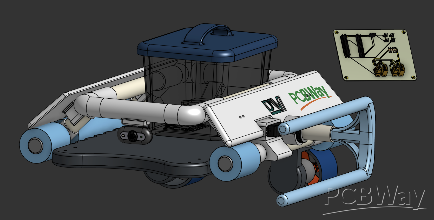
Project & Team Overview We are DEUROV, an underwater robotics team from Dokuz Eylül University. We design and build Remotely Operated Vehicles (ROVs). In our latest vehicle, we separated our electronic system into two distinct custom PCBs to isolate high-current power delivery from low-voltage logic and sensor data. This ensures system stability and prevents electrical noise in a tight underwater enclosure.
1. Power Distribution Board (PDB) This board manages the main power delivery of the vehicle.
Function: It takes the 21V input from the main battery and distributes it to the high-current ESCs (Electronic Speed Controllers) and thrusters.
Key Features: Designed with wide copper traces to safely handle high continuous currents (30A+). It includes an array of TVS diodes on the outputs to protect the entire system from inductive kickback generated by the motors and provides reverse polarity protection.
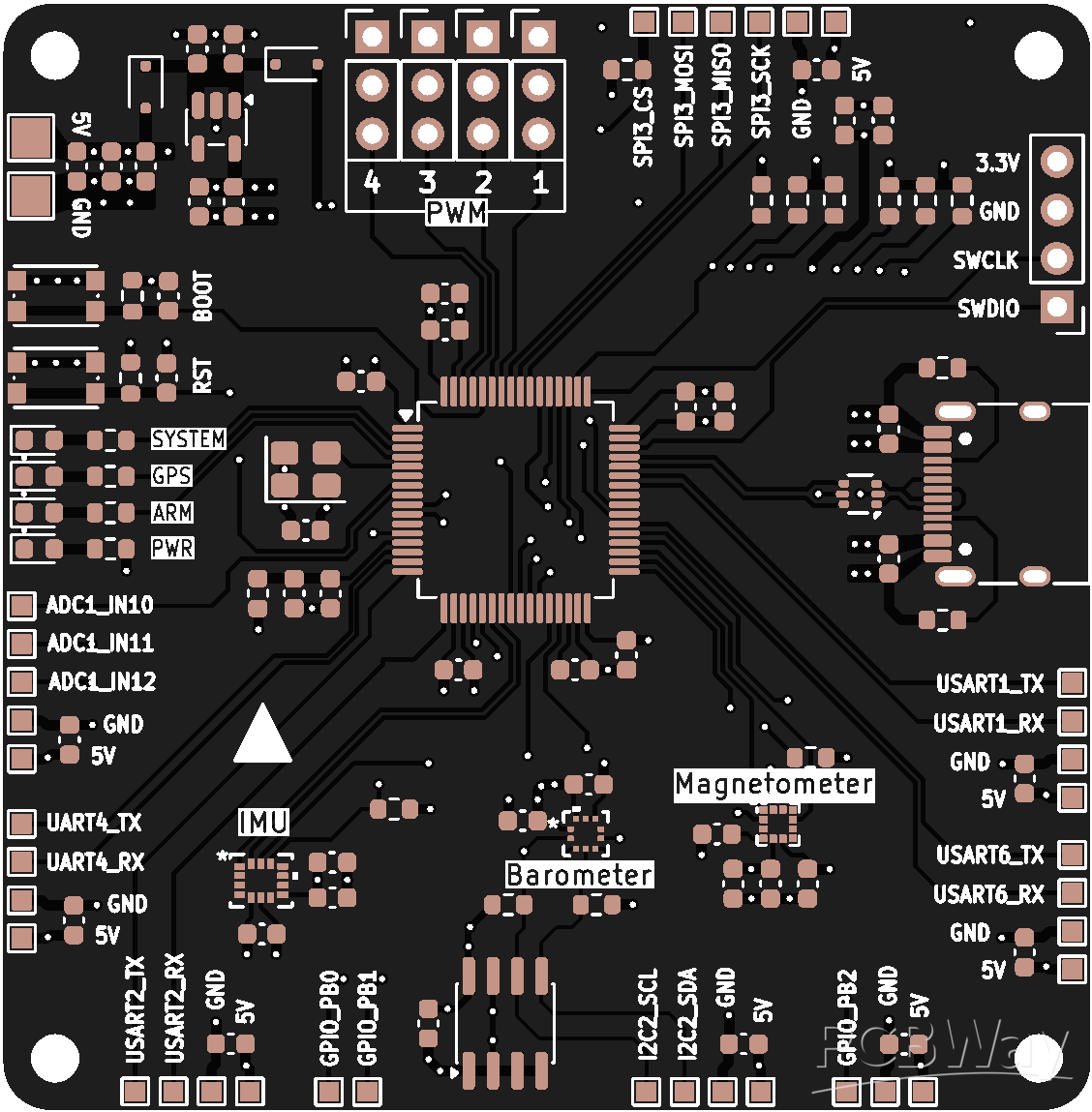
2.Main Control Board this is the central logic and communication hub of the ROV.
Function: It integrates all microcontrollers, sensors, and telemetry systems, completely isolated from the high-current noise of the PDB.
Key Features: It houses custom headers and routing for a Raspberry Pi 5 and an ESP32. It provides dedicated communication lines for the BNO080 IMU and depth/pressure sensors. Furthermore, it is specifically engineered to act as the master controller for our in-house hardware; it seamlessly interfaces with the custom LED driver circuits and critical leak detection systems that we manually prototyped and built on perfboards in our university lab. Finally, it features dedicated, noise-free signal routing for precise control of the ROV's servo motors.
1.Power Distribution Board
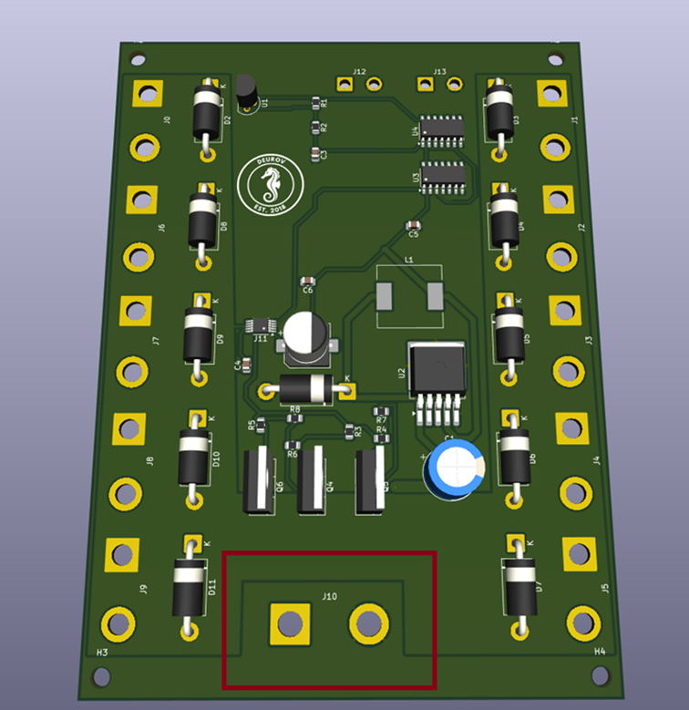
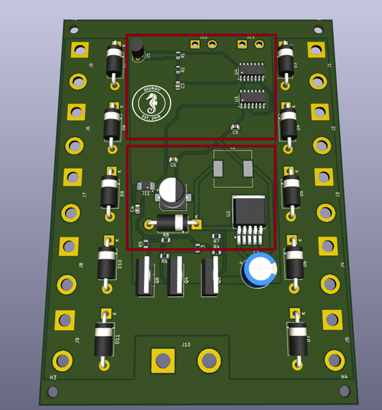
MAIN POWER INTAKE & HIGH-CURRENT ROUTING (XT90)
The core of our power delivery starts here. This heavy-duty XT90 input safely receives the raw 21V high-current surge directly from our custom lithium-ion battery pack. To handle the massive continuous current required by the thrusters (30A+) without overheating or trace degradation, we routed the main power lines using expansive polygon pours specifically on the Bottom Copper (B.Cu) layer. This wide-trace architecture strictly minimizes electrical resistance, prevents critical voltage drops, and acts as an integrated heat sink for the entire board.
ALWAYS-ON STANDBY & CONTACTLESS MAGNETIC SWITCHING This section solves one of the biggest challenges in underwater robotics: waterproof switching. Traditional mechanical switches require physical holes in the vehicle's hull, creating massive leak risks under high water pressure.
To completely eliminate leak points, we designed a contactless magnetic switching system powered by a continuous standby circuit. The integrated step-down regulator is always active, efficiently dropping the raw 21V from the battery to a stable 12V line. This 12V line is dedicated to keeping our Hall Effect sensor perpetually "awake" and monitoring, while drawing virtually zero power in standby mode.
To power up the entire vehicle, the operator simply swipes a magnet across the outside of our waterproof acrylic hull. The Hall sensor detects the magnetic field through the thick enclosure and instantly triggers the main MOSFET array. This provides us with a 100% waterproof, zero-wear power switch.
HIGH-CURRENT SOLID-STATE RELAY (PARALLEL MOSFET ARRAY) To safely handle the massive and dynamic power demands of our thrusters—which can draw anywhere from 30A up to 60A+ under water, we engineered a robust solid-state switching array utilizing three high-power N-channel MOSFETs in parallel.
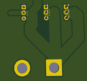
As clearly visible in our PCB routing, we strategically separated the high-current planes. The raw 21V current from the battery is delivered to the MOSFETs through a dedicated wide trace on the Bottom Copper (B.Cu) layer. Once the Hall Effect sensor signals our charge-pump gate driver, the MOSFETs open, and the immense power is seamlessly transferred to the motor outputs through a massive Front Copper (F.Cu) polygon pour.
This specific dual-layer wide-trace architecture is crucial. It completely prevents dangerous voltage drops, drastically minimizes electrical resistance, and allows the top copper layer to act as a giant integrated heatsink, safely dissipating the thermal load without relying on unreliable mechanical relays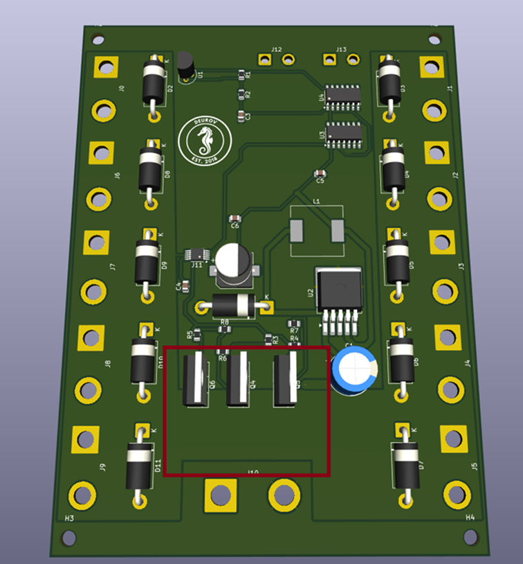 .
.
INDUCTIVE KICKBACK & SURGE PROTECTION (TVS DIODE ARRAYS) Protecting the system at the points where raw power is routed to the Electronic Speed Controllers and thrusters is critical. In sub-aquatic operations, rapidly decelerating or reversing heavy thrusters generates massive inductive kickback that can easily destroy the MOSFETs and logic circuits. To mitigate this, we implemented heavy-duty Transient Voltage Suppressor (TVS) diode arrays in parallel on every single high-current output. These diodes instantly clamp any reverse voltage spikes, guaranteeing the survival of our entire power switching architecture.
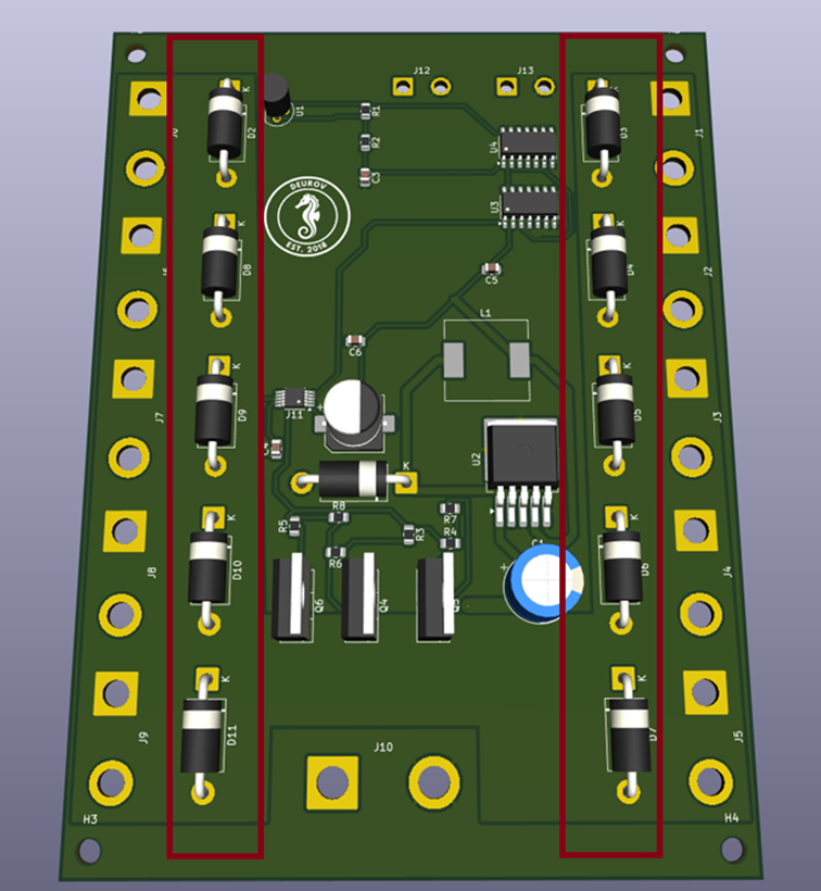
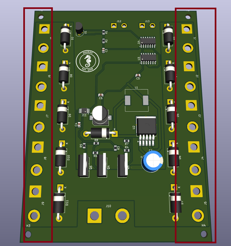
MODULAR ESC & THRUSTER OUTPUT TERMINALS The final destination of the power delivery system is this array of high-current output terminals distributed along the edges of the board. Our sub-aquatic vehicle utilizes multiple thrusters to achieve complex 6-DOF (Degrees of Freedom) maneuverability.
Instead of hard-wiring everything and creating a tangled mess inside the tight acrylic hull, we designed these modular, evenly spaced connection points for the +21V_motor_out and GND lines. This edge-routed layout allows us to neatly plug in individual Electronic Speed Controllers. It ensures a highly organized wiring harness, minimizes wire lengths to reduce resistance, and makes replacing a damaged thruster in the field incredibly fast and efficient.
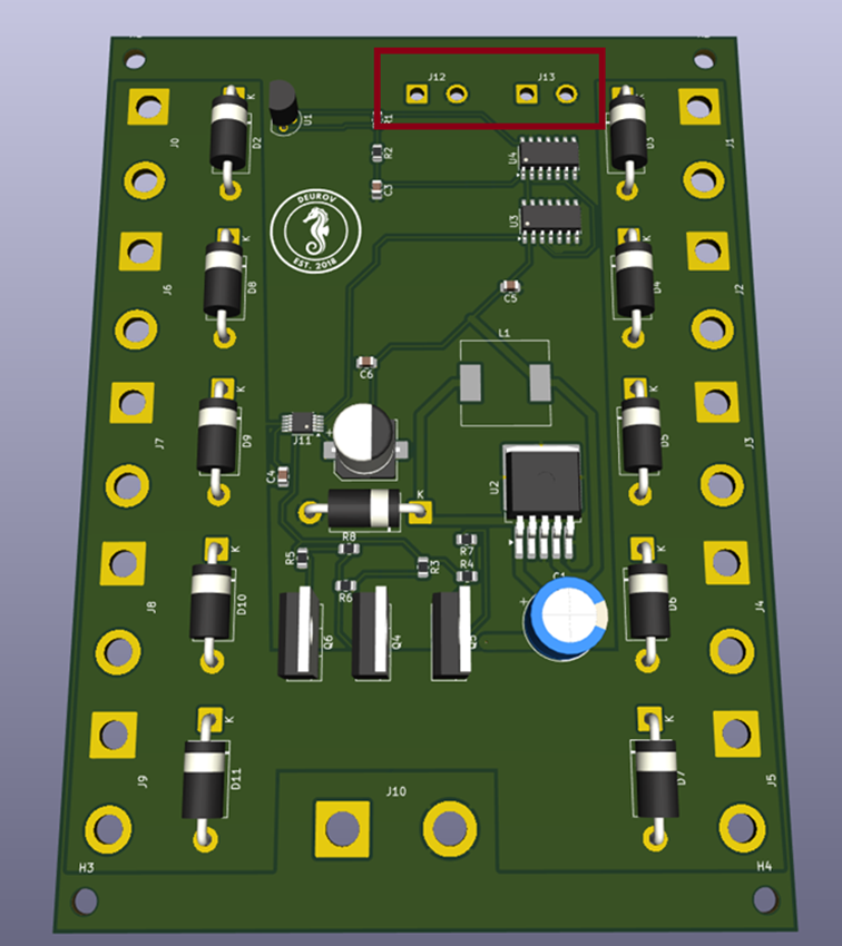
AUXILIARY POWER ROUTING (LOGIC & ILLUMINATION)
Beyond managing the high-current thrusters, the PDB also distributes power to our secondary systems. We designed two dedicated auxiliary output ports originating directly from our power plane. One port is designated to supply stable power to the Main Control Board, while the second port provides direct power to our custom sub-aquatic LED lighting system.
MANUFACTURING SPECIFICATIONS: 2 OZ COPPER REQUIREMENT For a sub-aquatic power distribution board handling continuous currents of 30A and dynamic spikes well beyond that, standard 1 oz copper prototyping is physically insufficient. To prevent trace delamination and catastrophic burnouts under heavy thruster loads, this PCB is strictly designed to be manufactured with a 2 oz copper thickness.
This precise specification across all high-current planes is not an aesthetic choice; it is a critical safety requirement. The 2 oz thickness drastically lowers trace resistance, preventing dangerous voltage drops. Furthermore, it allows the expansive Front and Bottom Copper polygon pours to act as highly efficient, integrated heatsinks. These industrial-grade manufacturing tolerances, combined with precise vias and robust solder masks, are absolute requirements to ensure the vehicle's electrical reliability and survivability in high-stakes competition environments.
2.Main Control Board
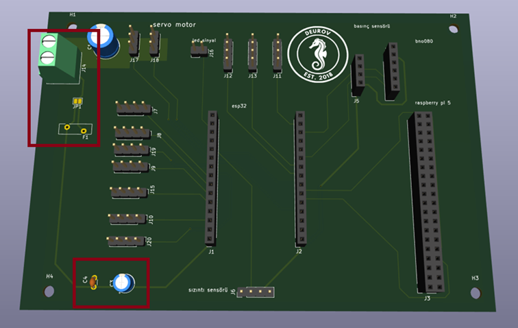
LOGIC POWER INTAKE & FAIL-SAFE PROTECTION The lifecycle of our logic system begins here, receiving a regulated 5V supply from the PDB. Because underwater competition environments are highly unpredictable, we implemented a robust fail-safe mechanism at the input. The power routes through a PTC fuse. In the event of a sudden short circuit or overcurrent, the PTC rapidly heats up, exponentially increasing its resistance to safely limit the current and protect our sensitive microcontrollers.
However, in high-stakes competition scenarios, we cannot afford to lose a mission due to a permanently damaged or locked fuse. To counter this, we strategically placed a physical jumper bridge parallel to the PTC. If the fuse fails during a critical moment, we can instantly bridge this jumper to bypass the fuse, restoring power immediately and keeping the ROV in the water without needing complex component replacements in the field.Furthermore, to guarantee absolute system stability, we positioned a combination of bulk and high-frequency decoupling capacitors immediately after the power intake. These capacitors act as a crucial localized energy reserve, preventing sudden microcontroller brownouts during unexpected load spikes, while actively filtering out any residual high-frequency noise traveling from the main power lines.
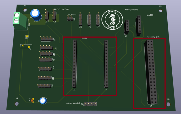
DUAL-PROCESSOR ARCHITECTURE (RASPBERRY PI 5 & ESP32) To handle the immense computational load of a modern ROV, we designed a dual-brain architecture. The expansive custom headers on the right accommodate a Raspberry Pi 5, which serves as the master computer—handling heavy tasks like real-time image processing, complex control loops, and surface telemetry. Working alongside it is an ESP32 microcontroller, acting as our real-time hardware interface. This separation ensures that the Pi’s operating system overhead never interferes with instantaneous hardware reactions.
PRECISION TELEMETRY & IN-HOUSE HARDWARE INTEGRATION A sub-aquatic vehicle is completely blind without pristine sensor data. We precisely routed dedicated, interference-free communication lines for our BNO080 IMU (for 6-DOF spatial orientation) and high-accuracy depth/pressure sensors. Furthermore, this section acts as the central hub for the custom hardware we built by hand in our university lab. It seamlessly interfaces with our perfboard-based LED lighting drivers and critical leak detection systems, bringing our custom in-house circuitry directly into the main control loop.
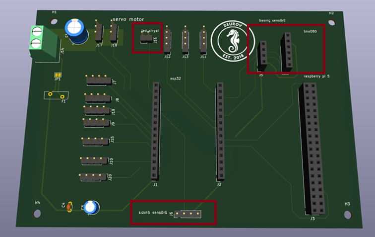
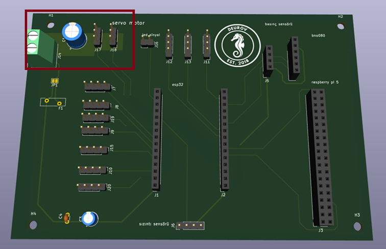
TEKNOFEST MISSION: MINI-ROV DEPLOYMENT & HIGH-CURRENT SERVO CONTROL One of our critical mission directives for the Teknofest competition requires our main vehicle to carry, and at a precise moment, deploy a secondary "Mini-ROV." This mini vehicle remains physically tethered and communicatively linked to the main ROV, but is controlled externally. To physically execute this vital deployment mechanism, we integrated two dedicated servo motor outputs.
Because high-torque servos draw severe, instantaneous current spikes when actuating under intense water pressure, standard PCB trace routing is entirely insufficient. To handle this, we engineered a dedicated high-capacity copper pour specifically for the servo power distribution, drastically reducing trace resistance. Furthermore, we integrated a massive 1000uF bulk capacitor directly onto the servo power rail. This acts as an immediate localized energy buffer. When the two servos are triggered to drop the Mini-ROV, this capacitor instantly supplies the burst current required, preventing any dangerous voltage sags (brownouts) that could otherwise crash or reset our main microcontrollers during the most critical phase of the competition.
PROJECT IMPACT & ACCELERATING DEVELOPMENT As a dedicated university robotics team deeply passionate about advancing sub-aquatic vehicle technology, our primary challenge is not engineering, but resources. Pushing the boundaries of underwater exploration requires specialized, high-power components and industrial-grade manufacturing. Unfortunately, the inherent costs of developing such advanced hardware on a strict student budget often slow down our research and development cycles. PCBWay's support would directly eliminate these financial bottlenecks, empowering our team to safely manufacture our custom circuits, meet our critical competition deadlines, and bring this complex ROV architecture to life much faster and more efficiently.
Apply for sponsorship >>- Comments(0)
- Likes(1)