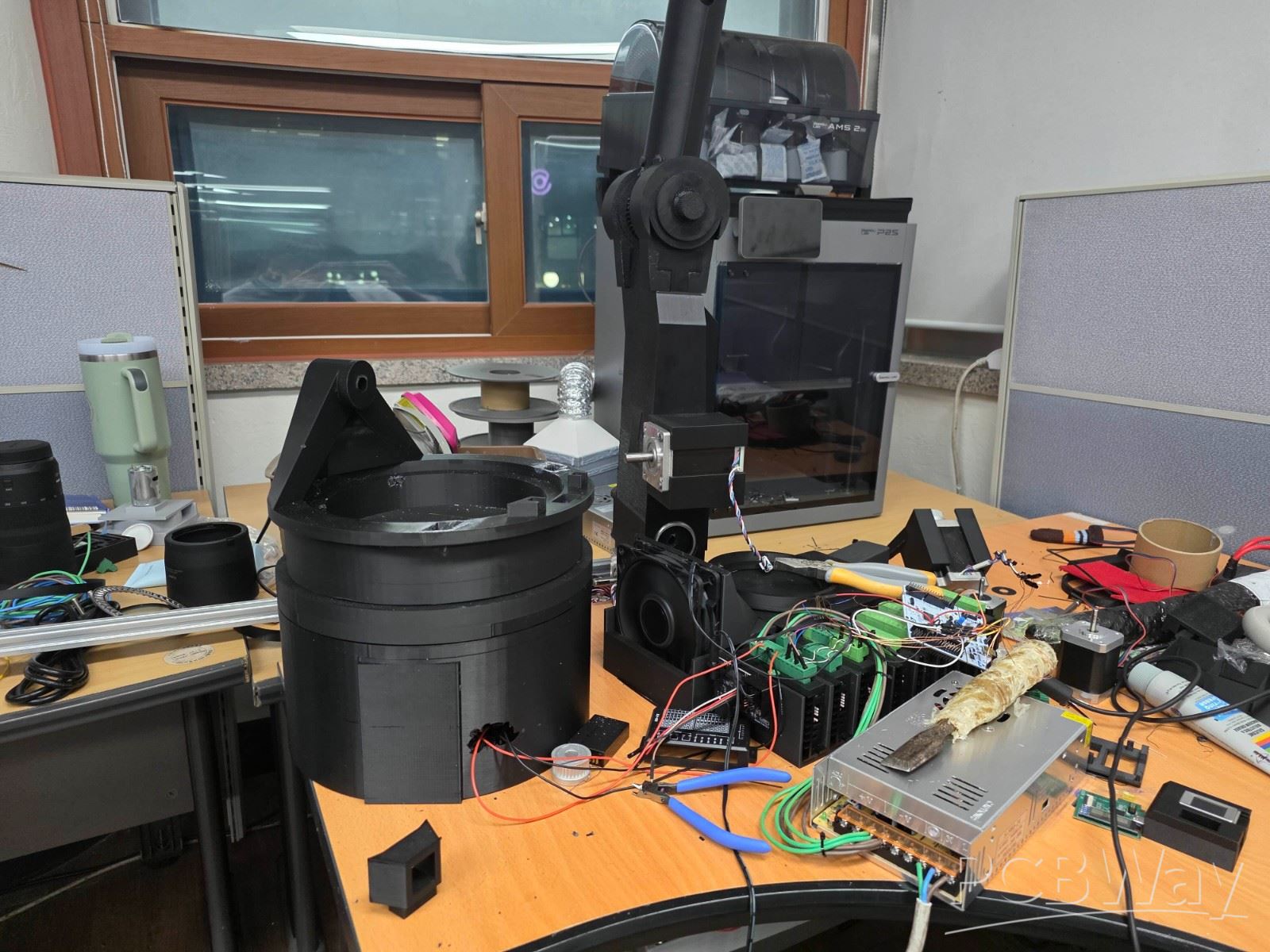
7 axis robotic arm
This project is a custom 7-axis robotic arm controller designed for a high-power stepper motor based robot arm. The goal of this project is to build a compact and expandable motion control board that can drive multiple robot joints while keeping the hardware structure clean, reliable, and easy to debug.
The controller is designed around an STM32 microcontroller, which handles real-time STEP/DIR signal generation and low-level motor control. An ESP32 is used as a higher-level communication and planning processor, allowing the system to receive motion commands and coordinate multi-axis movement. Each axis uses a dedicated stepper motor driver, and the board is designed to control up to seven axes independently.
One of the main challenges of this project is power distribution. Since the robotic arm uses multiple high-current motors, the PCB must handle a large motor power bus while still protecting the sensitive logic and control signals. To solve this, the board uses separated motor power routing, a solid ground plane, local decoupling capacitors near each driver, and wide copper areas for high-current paths. I also plan to reinforce the main motor power path with copper bus bars to improve current handling and reduce voltage drop.
The board also includes support circuits for practical robotic arm development, such as encoder feedback, mode selection pins, cooling fan control, and debugging interfaces. Magnetic encoders can be used on each joint to provide position feedback, making it possible to develop closed-loop control in the future.
This project is still under development, but the current prototype already includes the main control architecture, motor driver layout, power routing strategy, and mechanical integration tests. PCBWay’s PCB manufacturing and assembly service would be very helpful for improving the reliability and quality of the next revision, especially because this board requires accurate PCB fabrication, stable high-current traces, and good assembly quality.
Through this project, I want to create a powerful and practical robotic arm platform that can be used for motion control experiments, robotics research, and future automation projects.
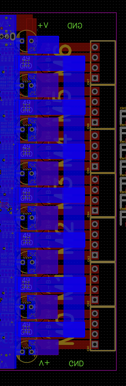
From now, Let me introduce my pcb layout
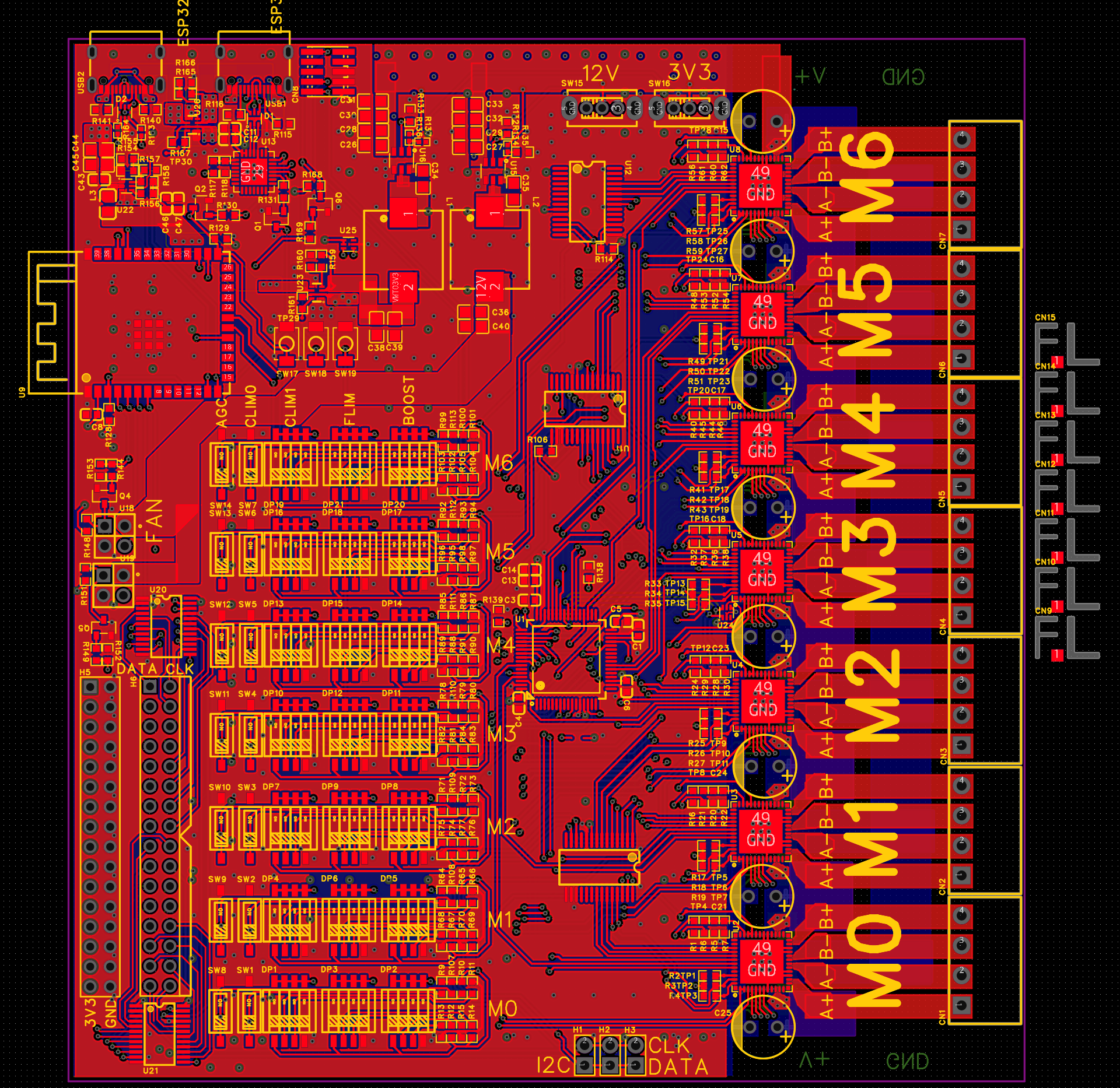
This is overall design. There is a ESP32 for high-level control. like cordinating.
In the middle, There is a STM32 for low-level control. like IK.
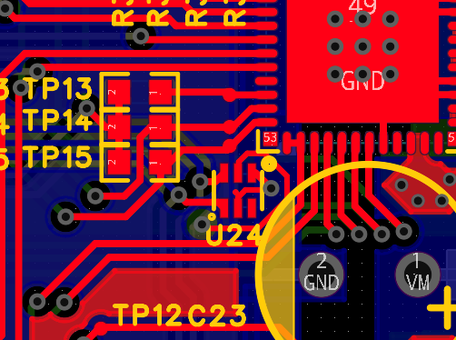
On bottom left side, there is a I2C mux for magnetic encoder. And there is a Driver Attribute which should not be changed during operation.
This board has FAN interface to cool itself down.
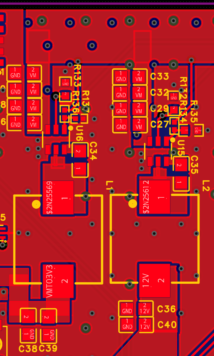
This is Each 12v, 3.3v 2.5A buck converter. Provides board a power from V_Motor(VM)
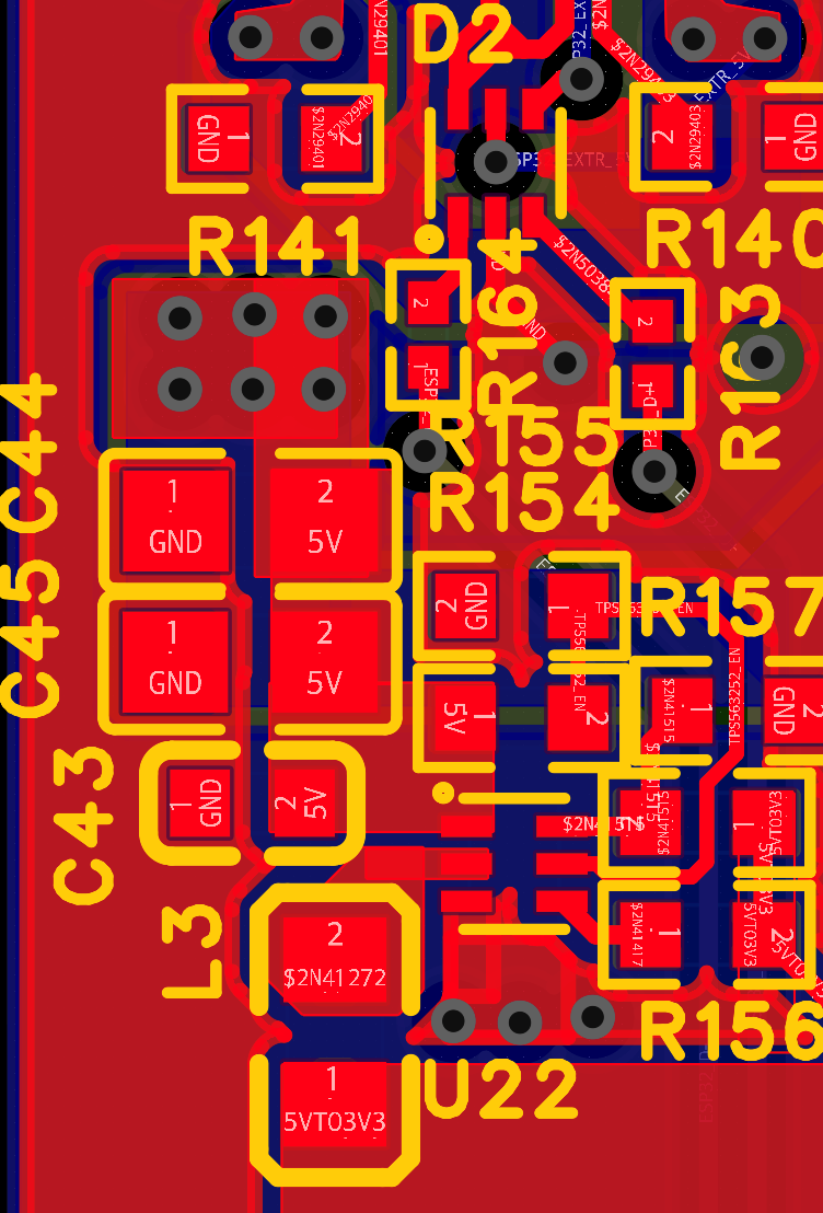
This is 5v to 3.3v 3A Buck converter. Provides power from usb VBUS.
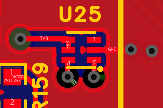
Because this board has two usb c port,
This board has power mux that switches between them.
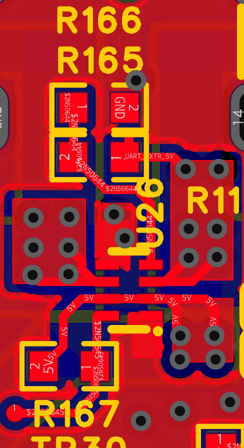
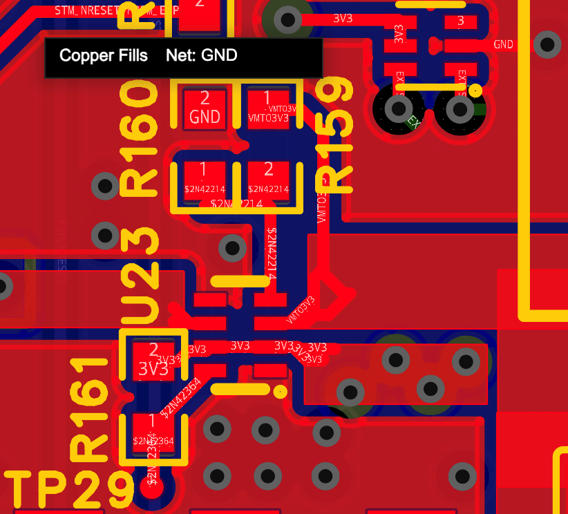
Also a 3V3 source selection mux is here
And there are two temperature sensor that monitor the temperature to decide fan duty cycle. One is next to M3 Controller, One is located between 3V3 power mux and VM to 3V3 Buck converter.
And due to high current rating, this board requires Copper current bus bar for power supplying. which will be soldered on the bottom side.
Apply for sponsorship >>- Comments(0)
- Likes(0)