


|
KiCADKicad
|
TLV320 ADC breakout
A small, ready-to-use TLV320ADC6140 board
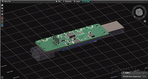
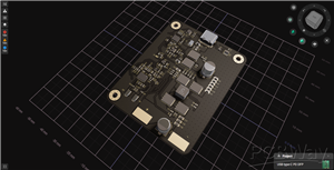
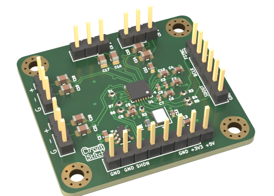
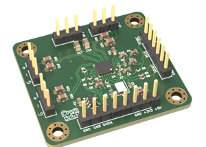
This is a four-channel line-level audio ADC on a small 4-layer board. It is built around the TI TLV320ADC6140.
I needed a real ADC to test audio capture on a Raspberry Pi Pico 2 (RP2350). TI's evaluation kit costs about $200 and comes with a large USB motherboard I didn't need. I wanted something small that just works. You plug in power, I2C and the audio bus, and it runs.
What's on the board
- TLV320ADC6140 four-channel ADC, up to 768 kHz and 32-bit
- 24.576 MHz TCXO (Abracon ASTX-H11, ±2.5 ppm) as the audio master clock
- Low-noise 3.3 V LDO (TPS7A2033) for the analog supply, powered from 5 V
- Four balanced line inputs on 3-pin headers: tip, ring and sleeve
- I2C pull-ups and a shutdown pull-down already fitted
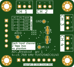
- Two solder jumpers that set the I2C address. The default is 0x4C.
- Test points for MCLK, AVDD and GND
How it works
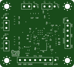
The Pico sends 5 V, 3.3 V and I2C through an 8-pin header (J1). It configures the ADC over I2C and then drives SHDNZ high to wake it. The ADC streams TDM audio out a 6-pin header (J2): FSYNC, BCLK and SDOUT, each with a ground pin beside it. Each signal line has a 33 Ω series resistor, so jumper wires to the Pico work cleanly.
Each input is balanced line level. It is AC-coupled straight into the ADC. The ADC clips at about 2 Vrms differential (about +8 dBu). There is no phantom power.
Firmware notes
- The input coupling caps are 4.7 µF. Set a longer quick-charge time than the default.
- Set the input impedance to 10 kΩ. This gives a 3.4 Hz high-pass corner.
Assembly
All the SMD parts are on the top side. The BOM and centroid files are included. The pin headers are through-hole and soldered by hand.
Ordering:
If using the PCBA service, these are the four layers to enter if prompted.
- L1: adc-breakout-F_Cu.gbr
- L2: adc-breakout-In1_Cu.gbr
- L3: adc-breakout-In2_Cu.gbr
- L4: adc-breakout-B_Cu.gbr
Licence:
The design is licensed under CERN-OHL-W-2.0 (similar to LGPL). See LICENSE in the GitHub repo.
TLV320 ADC breakout
Project images are for reference only. Actual production is based on the manufacturing files on the project page.
Please review the designer's notes (e.g., PCB thickness) and select the appropriate options.
PCBWay is not responsible
for issues caused by unsuitable parameter selections.
For more important ordering information, please refer to
Read More


Raspberry Pi 5 7 Inch Touch Screen IPS 1024x600 HD LCD HDMI-compatible Display for RPI 4B 3B+ OPI 5 AIDA64 PC Secondary Screen(Without Speaker)
BUY NOW


- Comments(0)
- Likes(0)
More by Kyle Falconer
-
-
-
-
AudioLink – USB & Bluetooth LE Audio / Auracast Receiver with Balanced Line Outputs (nRF5340)
339 0 1 -
-
-
-
Émetteur Récepteur Optique Expérimental (communication UART ATtiny + fibre optique)
392 0 1 -
SmallOLED - Live PC Stats, Animated Clocks & Audio Visualizer
1504 0 3