


I want to bury a reverse mount LED half way into the PCB and use the remainig PCB as a diffusor.
Here is the footprint and 3d view of the reverse mount package with a line on the Edge.Cuts layer:

since the smallest tool for z-axis milling is 0.8mm, the corner radius will be 0.4mm (is it correct?) I need to adapt the shape like this: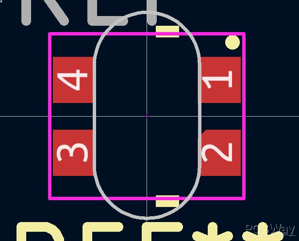
The line now is on the User.1 layer in the footprint editor, it will be exported to a milling layer. Obviously I want the whole area inside the oval to be milled, not just along the path, will this be understood? Is this the correct file preparation for z-axis-milling? Or should I rather mark the whole are which is going to be milled in z-axis? like this? 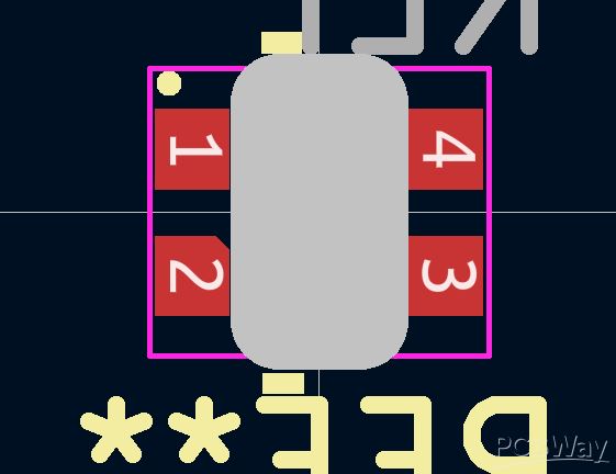
Is the 0.4mm radius also a limitation for cut outs or what's the limit there?