This guide is designed to help engineers and designers prepare CAD and STEP files that meet manufacturing standards. Following these design requirements prior to order submission helps prevent file rejections, shorten lead times, and reduce overall manufacturing costs.
Note: Material-specific values—including minimum hole size, internal radius, and thickness limits—vary by material and process.
Select the appropriate file format based on whether your part is flat or contains 3D forms/bends.

Unsupported Formats
Mesh Files: .stl, .obj, etc., are not accepted for flat/formed sheet cutting.
Raster Images: .jpg, .png, .tif, .bmp, etc. All raster artwork must be converted to vector geometry prior to submission.
A production file should contain only the closed cutting geometry required to manufacture the part. Clean all construction elements and annotations before exporting.
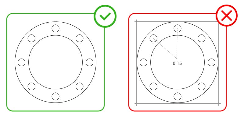
Remove all dimensions, title blocks, borders, guides, notes, and annotations.
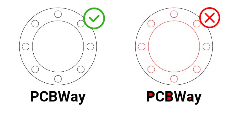
Convert all text to vector outlines (or explode/expand text in CAD). Editable fonts/text boxes cannot be recognized as cutting geometry.
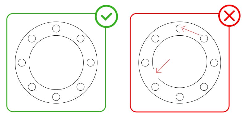
Every cut path must form a fully closed shape. Inspect geometry in wireframe/outline mode before export to detect unclosed paths or tiny gaps.
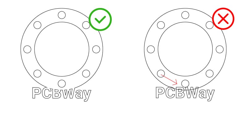
Delete duplicate, overlapping, or intersecting vector entities. In multi-entity geometry, duplicated lines can be interpreted as double-cutting paths and ruin cut quality.
Place all final cut paths on a designated cut layer. Move construction geometry or annotations to separate layers or delete them entirely prior to export.
Internal "islands" (e.g., the centers of letters like O, A, B, or donut-shaped cutouts) will become detached during cutting. Add bridges or stencil connections to retain them. Bridge width depends on material thickness.
Establish part envelopes and multi-part arrangements early to avoid sizing and production rejection issues.
Size limits vary by material and manufacturing process.
○ Minimal part size: 2mm (0.08in)
○ Maximal part size: 1000 mm (40in)
○ Minimal diameter: 0.3mm (0.01in)
These are general size restrictions; the specific restrictions vary depending on the material. For details, please upload your file and wait for an engineer to review it to determine if it is acceptable.
Do not share a cutting line between adjacent parts. Common-line cutting does not account for kerf, beam width, tool diameter, or stream width (which introduces a gap ranging from ~0.006″ to 0.012″ depending on material). Separate each part geometry according to process tolerance limits.
Materials with distinct surface finishes (e.g., brushed ACM, mirrored acrylic, textured ABS, hardboard) require specific top/bottom orientation. Save mirrored variations as separate files when orientation matters.
Check hole sizes, internal corners, narrow walls, and cutout density against process limitations before finalizing artwork.
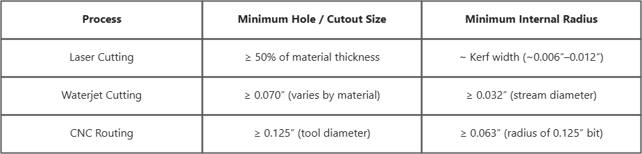
Extremely narrow walls or small isolated features tend to distort or overheat during cutting. Maintain minimum feature dimensions as specified for your target material and process.
Intricate patterns (e.g., grilles, speaker grates) increase cutting times and heat buildup, potentially causing warping or thermal marks in thin stock. If burn marks occur on fiber laser cut samples, increase the line/web thickness between cutouts.
Selection of laser, waterjet, or CNC routing depends on material composition, stock thickness, and required edge quality.
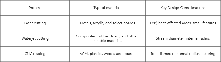
CNC routing uses a rotating bit for flatbed cutting on materials like ACM, plastics, wood, and boards.
Sizing Formula:
Dogbone Diameter ≥ Tool Bit Diameter+ 0.005″(0.13mm)
(Example: When routing with a standard 0.125″ bit, design your dogbone circles with a diameter of at least 0.130″.)
○Tab size: ~0.1875″ wide × 50% material thickness deep.
○Tabs are removed/sanded post-process and do not alter functional geometry.
○Edge geometry must allow at least 0.400″ spacing between vertex nodes for tab placement.
When submitting parts that require bending, folding, or forming, follow true sheet-metal modeling rules.
Each .step or .stp file must contain exactly one solid sheet-metal body. Multi-body solids or assemblies cannot be processed within a single part file.
Use dedicated sheet-metal design tools in your CAD software. Extruded solids or mesh objects are not valid substitutes for sheet-metal bodies.
Align at least one major flat face parallel to a primary CAD reference plane to ensure accurate flat-pattern unfolding.
Apply a sheet-metal rule matching your target material thickness, bend radius, and K-factor. Mismatched bend parameters cause open-contour or flat-pattern export errors.
Ensure the single sheet-metal body is selected before exporting. A file reading as 0″ × 0″ upon upload indicates an unselected body or missing solid geometry.
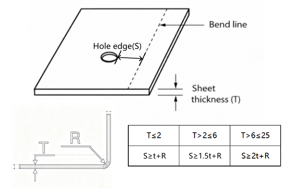
Placing holes or small features too close to a bend line will cause material stretching and feature distortion during die press braking. Follow these minimum spacing requirements:
Minimum Clearance= (2 × Material Thickness) + Bend Radius
(Holes placed closer than this limit will deform into ovals during bending.)
Minimum Flange Length= 4 × Material Thickness
(Flanges shorter than this limit cannot sit stably across the lower press brake die during forming.)
When a cutout intersects a bend line, add bend relief slots extending at least 1× Material Thickness beyond the bend line on both sides to prevent material tearing.
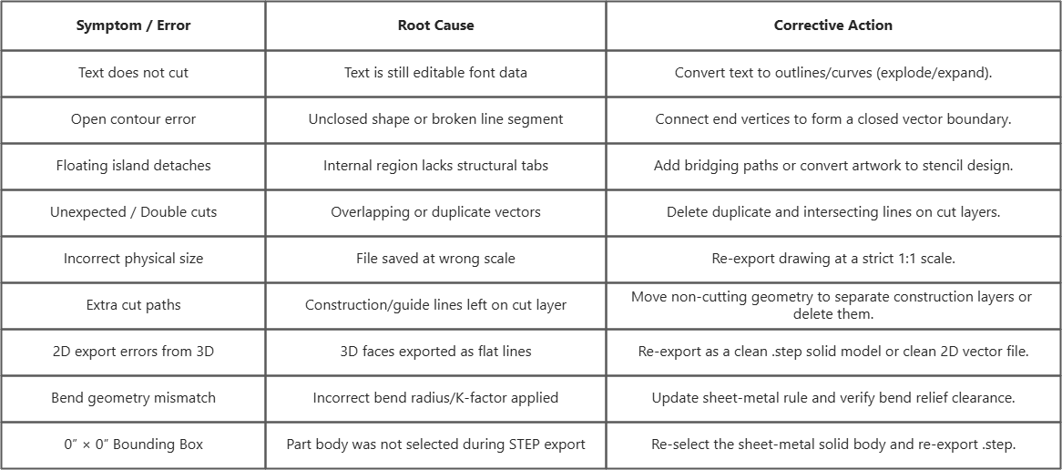
Verify the following before uploading your production file:



