This design guide provides structural engineers and mechanical designers with essential Design for Manufacturability (DFM) rules for Countersink (CSINK) and Counterbore (CBORE) holes in sheet metal fabrication and CNC machining. Following these geometric standards helps prevent knife-edge cutting, material tearing, bolt head protrusion, and engineering question (EQ) delays—ensuring a 100% first-pass review rate and fast delivery schedules.
1. Countersink (CSINK) vs. Counterbore (CBORE) Hole Explained
When designing parts for flush or recessed fasteners, choosing the correct hole geometry is critical to achieving functional performance and clean aesthetics.
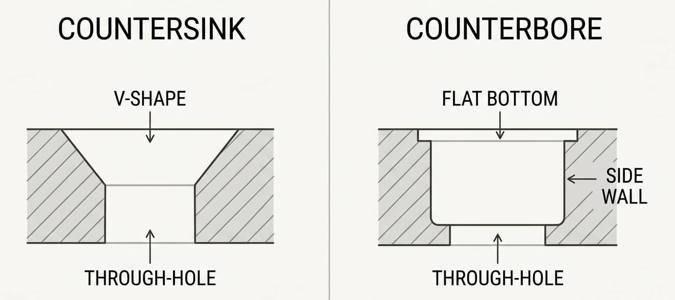
- Countersink Hole (CSINK): A conical basin cut into the surface to accept flat-head or undercut countersunk screws. The primary goal is to seat the screw head completely flush with or slightly below the outer surface of the part.
- Counterbore Hole (CBORE): A flat-bottomed, cylindrical enlargement of a hole designed to accommodate cylindrical screw heads, such as Socket Head Cap Screws (SHCS), allowing the fastener to sink entirely below the material surface.
2. Countersink Angle Standards: Metric vs. Imperial
A common cause of assembly interference is pairing screws with the wrong countersink angle. Always align your CAD design with the corresponding thread standard:
- 90° Angle (Metric Standard): The universal standard for all Metric countersunk screws (e.g., M2.5, M3, M4, M5, M6 per DIN 965 / ISO 7046).
- 82° Angle (Imperial/US Standard): The standard angle for Unified National Thread fasteners in North America (e.g., #4-40, #6-32, #8-32, 1/4"-20 UNC).
- 100° Angle (Aero & Thin Sheet Special): Used primarily in aerospace applications and ultra-thin sheet metal where shallow fastener heads are required to prevent punch-through.
3. Sheet Metal Countersinking: Critical DFM Rules
Processing countersinks on laser-cut sheet metal requires strict adherence to sheet thickness limits and feature clearances.
Rule 1: The "Knife-Edge" & Minimum Material Margin
Never allow a countersink to cut entirely through a piece of sheet metal. Leaving zero cylindrical wall thickness creates a razor-thin knife-edge at the bottom of the hole, leading to burrs, tool chatter, hole enlargement, and structural tearing during assembly.
- Minimum Web Thickness: Always preserve a straight cylindrical wall height of at least 0.50 mm (0.020") at the bottom of the countersink.
- Maximum Countersink Depth: The countersink head depth (H_cs) should not exceed 60% to 70% of the total sheet thickness (T).
Max Depth (H_cs) ≤ 0.70 × T
(Note: If sheet thickness is less than the countersink depth, evaluate using Press/Dimpled Countersinks or PEM Clinch Studs instead.)
Rule 2: Edge Distance & Bend Clearance
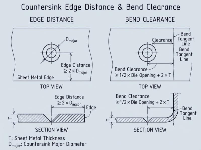
Tensile forces during bending can deform nearby countersunk holes, preventing flat-head screws from sitting flush.
- Distance to Edge: The distance from the hole axis to the plate edge must be ≥ 2.0 × Major Countersink Diameter (D_major).
- Distance to Bend Line: The edge of the countersink rim must be placed at a distance ≥ (1/2 × Bend Die Opening + 2 × T) away from any fold lines.
4. CNC Machined Countersink & Counterbore Hole Depth Rules
For solid CNC-milled parts, tool access and clearance tolerances dictate design quality.
- CBORE Diameter Clearance: Always size the counterbore diameter (D_cbore) 0.5 mm to 1.0 mm (0.020" to 0.040") larger than the actual screw head diameter to allow for socket driver clearance and anodizing/plating thickness.
- CBORE Depth Margin: Model the counterbore depth 0.2 mm to 0.4 mm deeper than the screw head height. This ensures the screw sits slightly below the surface, even with manufacturing tolerances on the fastener itself.
5. Recommended Countersink & Counterbore Drill Size Chart
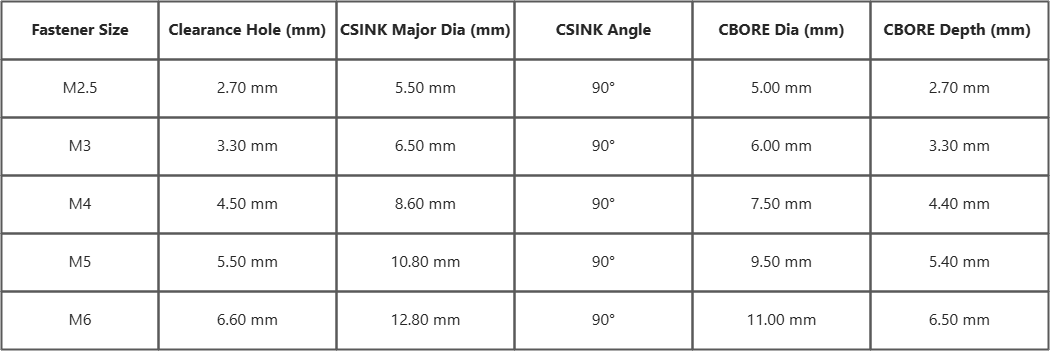
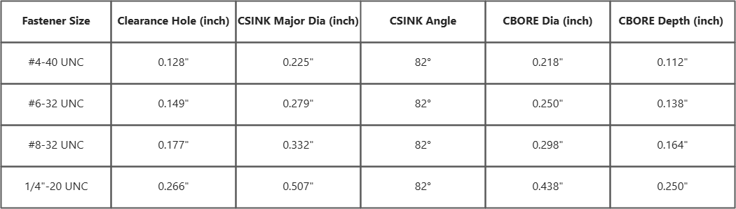
Use the following standard dimensions when modeling 3D CAD geometries for Metric and Imperial fasteners:
Metric Standards (90° Countersink / Standard Counterbore)
Imperial Standards (82° Countersink / Standard Counterbore)
6. CAD Modeling & 2D Drawing Setup
1. 3D CAD Representation: Model physical conical or cylindrical cuts directly in your STEP/IGES solid models matching the exact values in the size chart above.
2. 2D Drawing Callouts: Clearly annotate hole specifications using standard ANSI/ISO symbols:
- Countersink Symbol: v (e.g., DIA 4.5 THRU, CSINK DIA 8.6 x 90°)
- Counterbore Symbol: u (e.g., DIA 4.5 THRU, CBORE DIA 7.5 DEPTH 4.4)
3. Plating & Coating Allowances: If specifying thick powder coatings (60–120 µm), enlarge the CBORE diameter by an extra 0.2 mm or specify masking on the engineering drawing.
7. Pre-Manufacturing Checklist
Before submitting your CAD files for quotation, verify the following design details:
- Angle Matching Verified: Metric flat-head screws are specified with 90° countersinks; Imperial screws are specified with 82° countersinks.
- No Knife-Edges: Plate thickness exceeds countersink depth, leaving at least 0.50 mm of straight wall stock.
- Edge Distance Clear: Countersink rim to sheet edge is ≥ 2.0 × D_major.
- Tool Driver Room: Counterbore diameters provide adequate clearance for socket heads and wrench tools.
- Drawing Symbols Correct: 2D drawings contain explicit depth and diameter callouts.



