Summary: Nowadays USB port is used widely for data transactions between electronic devices and computers. In many scenarios, there is no need to communicate with the USB port directly, therefore electronic designers use USB to UART (RS232-Serial) converter chips, so the USB port is converted to a virtual COM port on the computer. In this article/video, I introduced a cheap USB to UART converter module that uses the MCP2200 chip from Microchip.
Nowadays USB port is used widely for data transactions between electronic devices and computers. In many scenarios, there is no need to communicate with the USB port directly, therefore electronic designers use USB to UART (RS232-Serial) converter chips, so the USB port is converted to a virtual COM port on the computer. The initial thought of many designers is to use FTDI chips to do the USB to UART conversion. There is nothing wrong with FTDI chips, however, they are expensive. In this article/video, I introduced a cheap USB to UART converter module that uses the MCP2200 chip from Microchip. The converter supports both 3.3V and 5V serial logic levels and uses three LED indicators for power connection, data transmission, and data reception.
The module supports the serial CTS and RTS pins, also six GPIOs that can be used for direct controlling of connected devices. The serial data of the module has been examined and decoded using the UART decoding feature of the Siglent SDS2102X Plus oscilloscope. So let’s get started!
A. Circuit Analysis
Figure 1 shows the schematic diagram of the USB to UART converter module. The schematic has been divided into a few parts for better visual inspection.
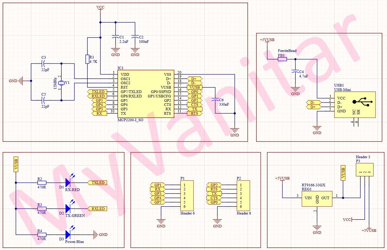
Figure 1, Schematic diagram of the USB to UART converter module
IC1 is the MCP2200 [1] USB to UART converter chip from Microchip. It supports full-speed USB up to 12Mb/s and it is available in a 20-lead SOIC package. So it is easy to solder this component for prototyping. It is also equipped with RTS and CTS pins and six GPIOs.
R1 is a pullup resistor for the reset pin and C1 and C2 are decoupling capacitors to reduce the supply noise. C3, C5, and Y1 build a clock generation unit. C6 reduces the VUSB rail noise.
USB1 is an SMD USB-mini connector for the USB cable connection. C4 and FB1 reduce the +5V USB supply noises. Figure 2 shows a picture of an SMD USB-B mini connector.
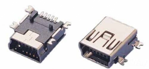
Figure 2, An SMD USB-mini connector
REG1 is the RT9166-33GX [2], that is a linear 3.3V regulator in a small SOT-89 package. According to the datasheet: “The RT9166/A series are CMOS low dropout regulators optimized for an ultra-fast transient response. The devices are capable of supplying 300mA or 600mA of output current with a dropout voltage of 230mV or 580mV respectively. The RT9166/A series is optimized for CD/DVD-ROM, CD/RW, or wireless communication supply applications. The RT9166/A regulators are stable with output capacitors as low as 1μF. The other features include ultra-low dropout voltage, high output accuracy, current limiting protection, and high ripple rejection ratio. The devices are available in fixed output voltages range of 1.2V to 4.5V with 0.1V per step. The RT9166/A regulators are available in 3-lead SOT-23 (RT9166 only), SOT-89, SOT-223, TO-92, and TO-252 packages”.
P3 is a 3-pin male-header that allows the user to switch between 3.3V and 5V logic levels, just by using a jumper. D1, D2, and D3 are three SMD LEDs that indicate the correct USB cable connection, data transmission, and reception. R2, R3, and R4 are used to limit the current of the LEDs.
B. PCB Layout
Figure 3 shows the PCB layout of the USB to UART converter module. It is a two layers PCB board and all component packages are SMD (except pin headers).
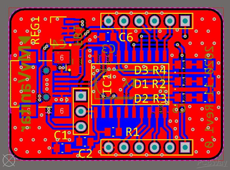
Figure 3, The PCB layout of the USB to UART converter using MCP2200
Figure 4 is a separate view of the top and bottom layers, so the red layer is the top and the blue layer is the bottom.

Figure 4, A separate view of the top and bottom layers of the PCB
When I decided to design the schematic and PCB for this project, I realized that I don’t have the component libraries of IC1[3] and REG1[4] in my component libraries storage. So as usual I decided to go with the SamacSys IPC rated component libraries and installed the missing libraries (schematic symbol, PCB footprint, 3D model) using the free SamacSys tools and services. There are two options to import the libraries into the Electronic designing CAD software: you can visit the componentsearchengine.com and download and import the libraries, or you can use the SamacSys CAD plugins and directly search/import the models into the design environment. Figure 5 shows all supported electronic designing CAD software [5], as it is clear all known software are supported. I use Altium Designer, so I searched and installed the missing libraries using the SamacSys Altium plugin (Figure 6) [6].

Figure 5, All supported electronic designing CAD software by the SamacSys plugins

Figure 6, Selected component libraries in the SamacSys Altium plugin
C. Assembly
Figure 7 shows a top view and figure 8 shows a bottom view from the assembled PCB board. The PCB boards have been fabricated by PCBWay. I got up to 10 boards with no price change. The quality of the copper, silkscreen, and solder mask was good, so I had no problem with soldering the components at all. The smallest package size of a component is 0805.
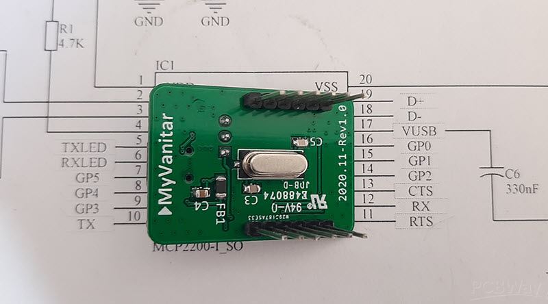
Figure 7, A top view from the assembled PCB board

Figure 8, A bottom view from the assembled PCB board
D. Test and Measurement
After you finished the soldering (or received the assembled board), you should connect the module to the computer and configure the MCP2200 chip, if it is necessary. Microchip provided a utility software to configure the chip [7], named “MCP2200 configuration utility”. Figure 9 shows a screenshot of the utility software. In my case, on the first try, LEDs were not blinking, so I had to enable the blinking in the configuration.

Figure 9, Microchip MCP2200 configuration utility
Figure 10 provides the wiring diagram of the module. With this guide, you should not have any problem with connections and wirings.

Figure 10, Wiring diagram of the USB to UART module
I connected the RX signal of the module (computer is the transmitter) to the Siglent SDS2102X Plus oscilloscope [8] to examine the signal and decode the data. At the same time, I played with the jumper to switch between 3.3V and 5V logic levels. Figure 11 shows the UART signal and the decoded data and figure 12 shows the same signal with the enabled result-list that can be used to examine the timing, errors .. etc. For more details please check the video.

Figure 11, Decoded RX-UART data using the Siglent SDS2102X Plus oscilloscope

Figure 12, Decoded RX-UART data using the Siglent SDS2102X Plus oscilloscope (enabled result-list)
E. Bill of Materials
Figure 13 shows the bill of materials for this project.
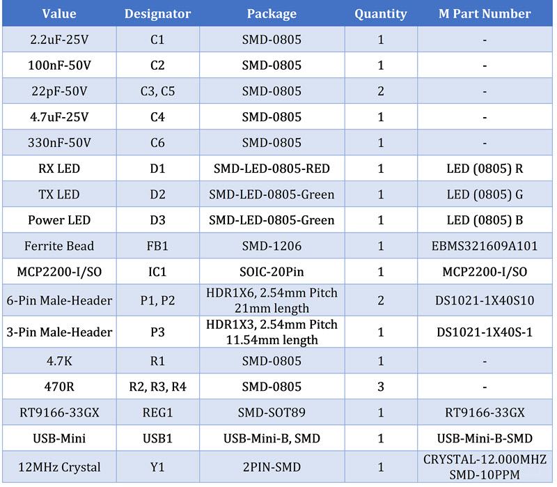
Figure 13, Bill of materials
References
[1]: MCP2200 datasheet: https://www.mouser.se/datasheet/2/268/22228A-81933.pdf
[2]: RT9166-33GX datashet: https://www.richtek.com/assets/product_file/RT9166=RT9166A/DS9166A-23.pdf
[3]: MCP2200 schematic symbol, PCB footprint, and 3D model: https://componentsearchengine.com/part-view/MCP2200-I%2FSO/Microchip
[4]: RT9166-33GX schematic symbol, PCB footprint, and 3D model: https://componentsearchengine.com/part-view/RT9166-33GX/RICHTEK
[5]: Electronic designing CAD software plugins: https://www.samacsys.com/library-loader-help
[6]: Altium Designer plugin: https://www.samacsys.com/altium-designer-library-instructions
[7]: Microchip MCP2200 configuration utility: https://ww1.microchip.com/downloads/en/DeviceDoc/MCP2200%20Configuration%20Utility%20v1.3.1.zip
[8]: Siglent SDS2102X Plus oscilloscope: https://www.siglenteu.com/digital-oscilloscopes/sds2000xp
https://ww1.microchip.com/downloads/en/DeviceDoc/MCP2200%20Configuration%20Utility%20v1.3.1.zip


