Summary: A good engineer would like to control the switching and protection of the electrical circuit. One of the basic components to use in such functions is the relay, and for this article, we will introduce types of relays to ease their job.
A good engineer would like to control the switching and protection of the electrical circuit. One of the basic components to use in such functions is the relay, and for this article, we will introduce types of relays to ease their job.
In power systems, relays are treated as one of the essential electrical components in applications that are accompanied by demands for switching and protection of their control circuits and other connected electrical loads and components. The relays operate such that they open or close their contacts whenever connected to the voltages or currents. This article will briefly introduce you to several types of relays in the market so that when designing your engineering projects for power systems, you can no longer fall short of such relay components. Let us dive into the content of this article!
Several types of relays are classified into several categories based on their electrical and construction properties. Each type of relay has a particular application, and you should make the correct selection every time you want to use the relay in the electrical circuit. Relays can be categorized as.
A relay has a pole and a throw. Poles are the number of switches in a given relay, and throws are the number of electrical circuits controlled per pole. Therefore, one category of relays is the poles and throws, where a relay is classified based on the number of poles and throws inside its electrical circuit.

Figure 1:Pole and Throw by Simon Mugo
Under this category, you will come across the following types of relays:
A single pole means the relay can only control a single circuit, and a single throw means the relay has only a single point of conduct. The diagram below shows what it looks like.
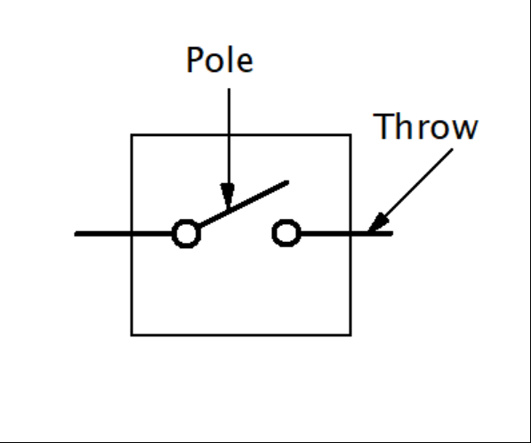
Figure 2: Single Pole Single Throw Relay by Simon Mugo
A single pole means controlling one circuit at a time, while the double throw indicates that the relay has two conduction points. Its diagram is shown in the figure below.

Figure 3: Single Pole Double Throw by Simon Mugo
The relay has a double pole, which means it can control two electrical circuits that are completely isolated. The single throw shows that every pole has a point of conduct that connects to complete the circuit. This type of relay can be important when simultaneously switching two circuits by offering an open or closed circuit. Its diagram is shown below.

Figure 4:Double Pole Single Throw by Simon Mugo
It has a double pole that controls two different circuits, while each double pole can hold two separate conduct points, hence a double throw. It can be said to be two SPDTs with simultaneous switching modes. Check the image below.

Figure 5:Double Pole Double Throw by Simon Mugo
It is good to note that you will come across relays with up to 12 poles in the market.
Here, the relays are classified considering their working and operating principles. They include:
Electromechanical Relays
Abbreviated as EMR. They are made up of mechanically movable contact and an electromagnetic coil. The energizing of the loop produces magnetic fields that attract the relay’s movable contact. The magnetic field is lost on de-energizing the ring, and a spring on the relay returns the armature to its original position. It can be used in both AC and DC sources. The difference between the AC and DC application relays is the coil construction. You will meet a freewheeling diode for the DC coil, which protects the circuit against back EMF and coil de-energization.
The EMR pol
arity is not something to worry about because it can function in both directions, but if there is the presence of the back EMF, then it is very important to consider the polarity for protecting the freewheeling diode. Its disadvantage is that it produces arcing when breaking, hence high resistance and low lifespan.
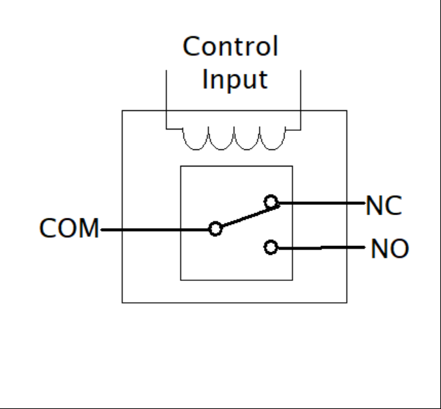
Figure 6:EMR Courtesy of Simon Mugo
Solid State Relays
Abbreviated as SSR, it is built using semiconductors in place of the mechanical parts and works on the principle of circuits of low voltage isolation from those of high voltage by using the optocoupler. Applying the control input to the SSR lights up an LED that produces infrared light. The directed light is received by a device made of a photosensitive semiconductor, which helps convert the produced light signals into electrical signals that switch the electric circuit.
This type of relay operates at a higher speed and low power consumption compared to an electromechanical one. Its lifespan is longer, too, since the relay does not experience burnout. It has the disadvantage of the voltage drop across its semiconductor, leading to power loss.

Figure 7: Solid-State Relay Courtesy of Simon Mugo
Reed Relay
This consists of an electromagnetic coil with a flywheel diode for the back EMF and reed switch. Reed switches are built using metal blades that are built using ferromagnetic material that is sealed in a tube made of glass that supports the edges. This glass is full of inert gas.
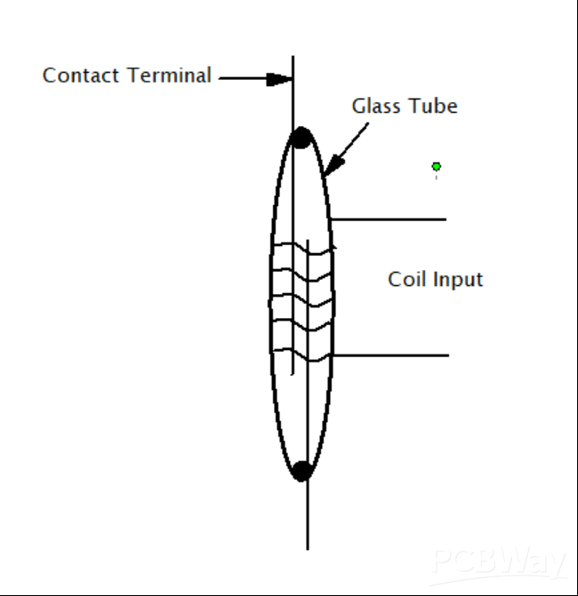
Figure 8: Reed Relay Courtesy of Simon Mugo
The energization of the coil makes the ferromagnetic metals attract each other, closing the circuit.
Hybrid Relay
This is a combination of the EMR and the SSR. The hybrid relay is significant in overcoming the power-wasting challenges of the SSR and the arcing problem associated with the EMR. The switching is done using the relay control circuit. The SSR takes the load current, hence eliminating the arcing problem. The control is used to energize the EMR coil, closing its contact without arcing since the connected SSR receives the load through a parallel connection. Immediately, there is the settlement of the EMR contacts; the next action is the removal of the SSR. Here, the EMR is used to contact the whole load, eradicating the power loss associated with the SSR.

Figure 9:Hybrid Relay Courtesy of Simon Mugo

|
V23079D1001B301TE Connectivity Potter & Brumfield Relays
|
x 1 |


