1. Blog>
  2. Advanced PCBs common laminated structure design template

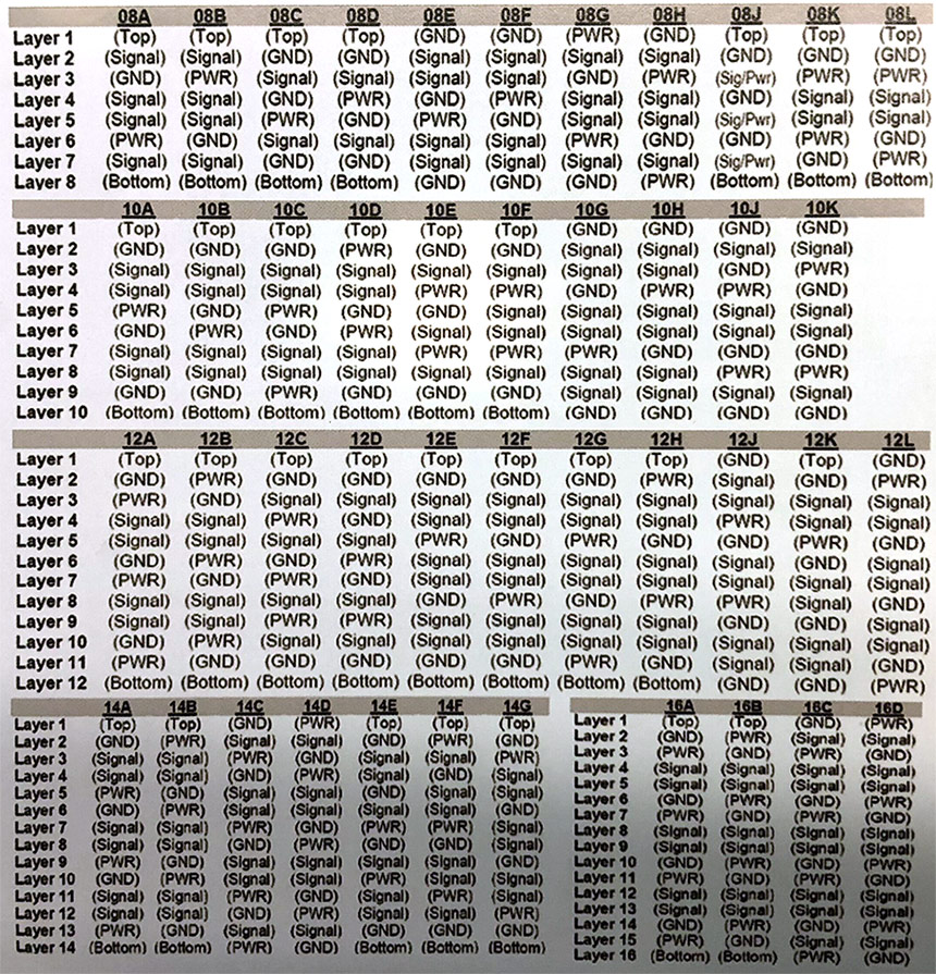
Advanced PCBs common laminated structure design template

by: Aug 08,2019 2512 Views 0 Comments Posted in PCB Basic Information

Advanced PCBs laminated structure PCB design template

1. PCB stack method is recommended as Foil superposition method

2. Minimize the use of PP and CORE models and types in the same stack (no more than 3 PP layers per layer).

3. The thickness of PP medium between 3 and two layers should not exceed 21MIL. (thick PP dielectric processing is difficult. Generally, a core panel will be added, resulting in the increase of actual laminated number, which will increase additional processing cost).

4. PCB outer layer (Top, Bottom layer) generally select 0.5OZ thickness copper foil, the inner layer generally select 1OZ thickness copper foil.

General description: according to the current size and line thickness determines the thickness of copper foil, such as the power supply board uses 2-3OZ copper foil, the common signal board generally choose 1OZ copper foil, thin wire may also use 1/3QZ copper foil to improve yield rate; while avoiding the core board inconsistent use both sides of the inner layer copper foil thickness.

5. The distribution of wiring layer and plane layer of PCB board requires symmetry from the center line of PCB board stacked, including the number of layers, the distance from the center line, the copper thickness of wiring layer, etc.

Note: the PCB stack method needs symmetrical design. The symmetrical design refers to the thickness of the insulation layer, the prepreg category, the thickness of the copper foil, and the type of the graphic distribution (the large copper foil layer, the line layer), which is symmetrical with the center line of the PCB as far as possible.

6. The design of the line width and the thickness of the medium needs to have sufficient allowance to avoid the design problems such as SI.

The stack of PCB consists of the power layer, the stratum and the signal layer. The signal layer, as its name implies, is the wiring layer of the signal line. The power layer and stratum are sometimes referred to as plane layers.

In a small number of PCB designs, we use the power supply ground plane wiring or the power grid and the ground network in the wiring layer. For this hybrid type of level design, we call it the signal level.

Advanced PCBs common laminated structure design template 

structure_template.jpg

4+6+4 HDI stackup Layer buildup/stackup reference

LayupConstruction.jpg

Join us
Wanna be a dedicated PCBWay writer? We definately look forward to having you with us.
  • Comments(0)
You can only upload 1 files in total. Each file cannot exceed 2MB. Supports JPG, JPEG, GIF, PNG, BMP
0 / 10000
    Back to top