


RMSE22 IIT Roorkee Motorsports
PROJECT DESCRIPTION
About Us-
IIT Roorkee Motorsports is the official Formula Student Electric team of IIT Roorkee which participates in the world’s largest Inter-Collegiate Engineering competition conducted by the Formula Student and FSAE by designing and fabricating an open-wheel formula-style electric race car. Our passion is not for cars alone - it is fuelled by our desire to use engineering and technology to change the mobility sector in India.
The team has participated in Formula Student competitions every alternate year - Formula Student UK - 2013 with a Hybrid Car, FSAE Australasia in 2015 with our first fully Electric car, and Formula Green in 2017. The team participated in Formula Green 2020 at Coimbatore, and Formula Bharat 2020, which was conducted remotely due to the pandemic. Continuing the legacy, the team is now gearing up to participate in Formula Green 2023 strong>Formula Student UK 2023.
Our recent achievements include:
· 3rd position in the overall competition and in the Engineering Design event at Formula Green 2020.
· Overall 6th position amongst 23 teams at Formula Bharat 2021 which was held online due to the pandemic.
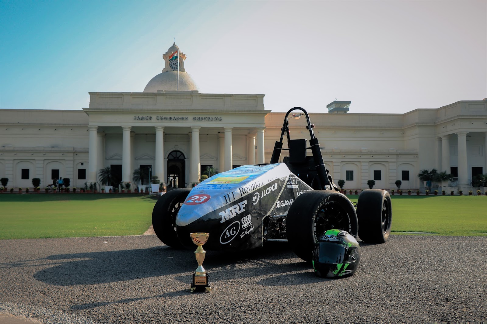
RMSE19 - Last manufactured car
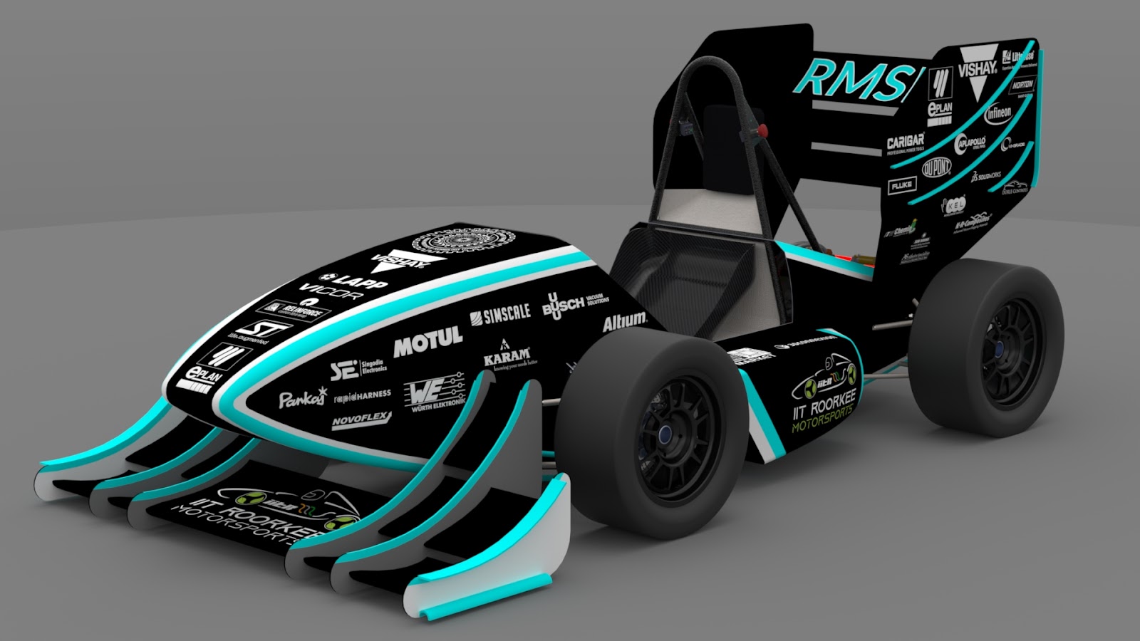
RMSE22- latest
Our website and social media can be found here:
IIT Roorkee Motorsports
IIT Roorkee Motorsports - Home | Facebook
IIT Roorkee Motorsports: My Company | LinkedIn
Our Next Project- RMSE22
- Top Speed: 160 km/h
- 0-100 km/h in 2.9 sec
- Weight without Driver: 229 kg
- Peak Motor Power: 100 kW
- Peak Motor Torque: 230 Nm
- Battery Capacity: 8.55 kWh
- Premiere inclusion of Aerodynamic Devices with considerably greater downforce
- Radical redesign of chassis with significant weight reduction
- Implementation of Telemetry data analysis for overall performance optimization
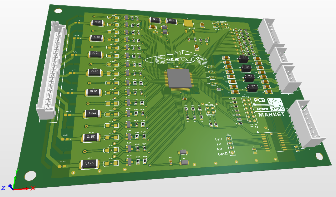
BMS
We design a Battery Management System in-house and solder the various components on the manufactured PCB. All of it is done by the team itself. It is a very crucial element in the vehicle because Li-ion batteries are sensitive and have to be managed properly to ensure the safety of the vehicle and the battery pack. We use bq76 IC by TI in our BMS. For our next project RMSE22, we are working on a 128S 6P battery pack design. We will have 8 PCBs and each PCB will monitor 16 cells.
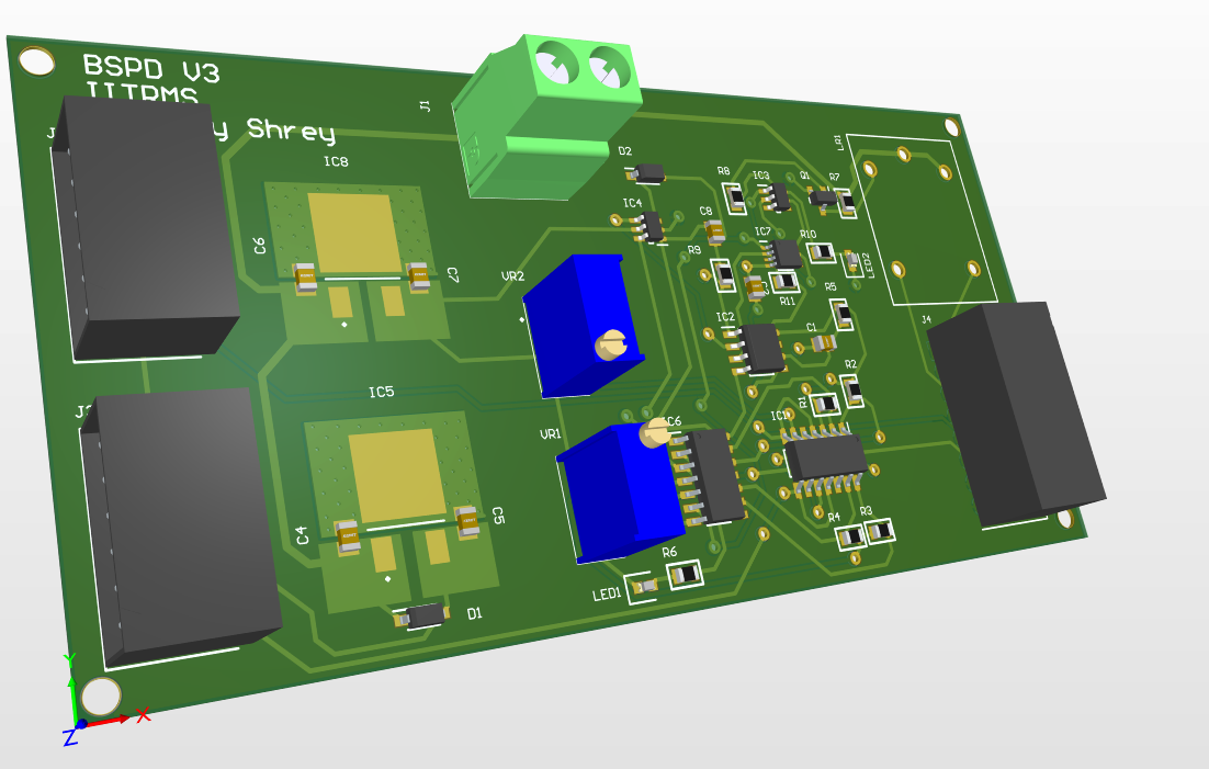
Brake System Plausibility Device (BSPD)
The BSPD is used to detect hard braking. It receives signals from a pressure sensor (that checks whether the brake pressure is within the threshold limit of 30 bars) and from a current sensor that is used to check the power delivered to the motors. If an unwanted value is received from any of these sensors for more than 500 ms, the BSPD generates an error signal which opens the shutdown circuit for the next 10s.
Discharge
To ensure proper braking and stop of a car we need to discharge the motor capacitor after the car has stopped. We have designed a PCB to implement the discharge functionality within 15 seconds. This PCB also contains a part of the pre-charge circuitry which charges up the motor capacitor approximately within 3 seconds using alternate paths depending on the charge of the capacitor. Moreover, additional functionalities like Tractive System Active Light are also implemented which is an indicator of different states and errors of the car.
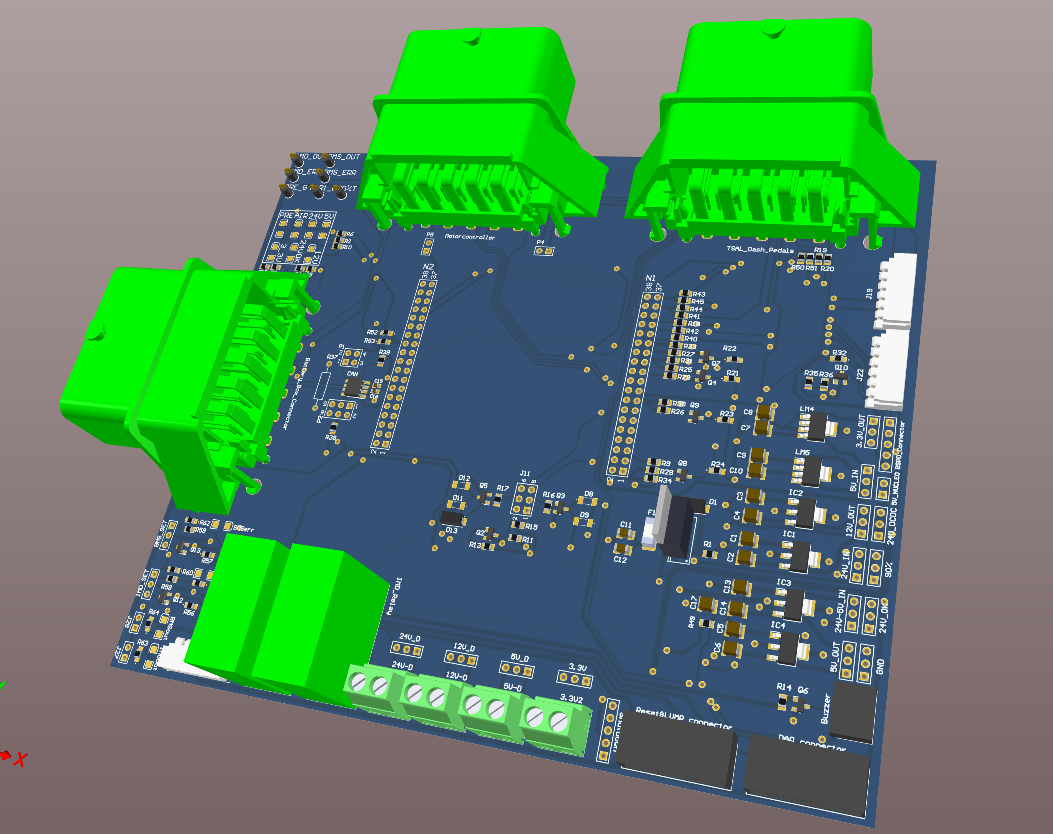
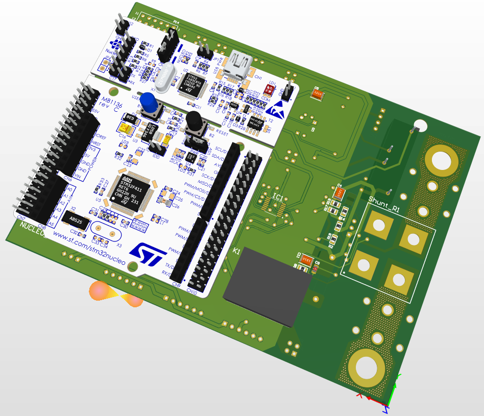
Power-Control Card
The Control Card receives signals from BMS, IMD, BSPD, APPS, few other PCBs, etc and generates the necessary response signals to control the shutdown circuit and communicate with other subsystems. It has a Nucleo as a central microcontroller through which additional functionalities and safety checks are implemented.
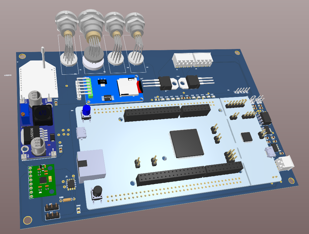
Data Acquisition-
Since our car consists of many sensors and actuators that need to be controlled periodically, we have designed a PCB for Data Acquisition it consists of various connectors to different sensors and processes them with an onboard Nucleo. It also has connectors to display data on the dashboard and we can wireless access the data using telemetry.
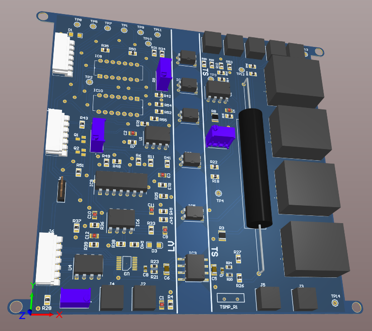
HV-LV
For RMSE’22 we design an HV-LV PCB for calculating the state of charge of battery through sensing of voltage and current by using AMC1200 and its output is given to the ADS8354 which converts this output to digital, now this output of ADS8354 works as the input to NUCLEO board, which we program in a way that it gives the SOC(state of charge) of the battery remaining. Apart from these, there are various other components used in this PCB like relays, CAN transceivers, and ICs. The PCB is well soldered and tested to ensure that it's working properly and not causing any damage to the car.
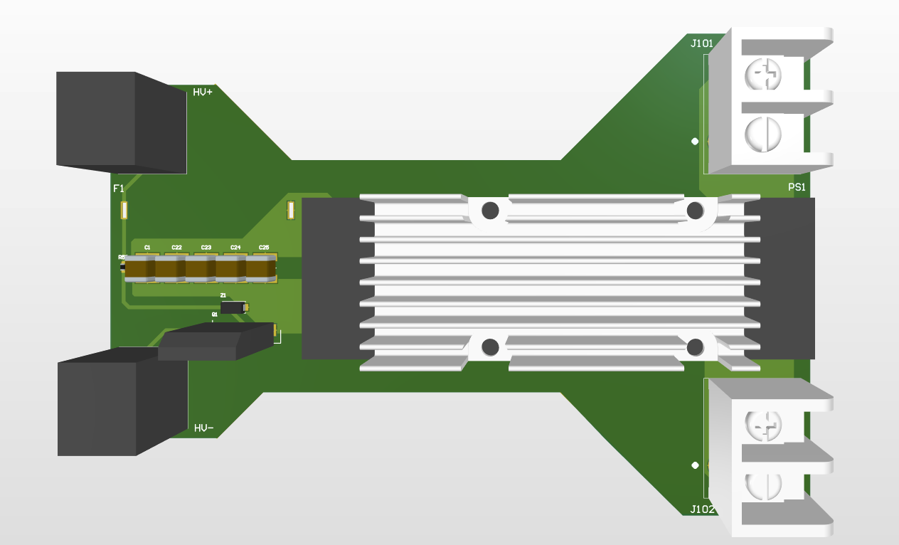
BCM
Since our car’s battery is too high, we need to step down the voltage for components to work properly. We can directly convert high voltage 400-700 V to low voltage around 48 V with the help of the BCM4414 bus converter along with filter circuits and reverse polarity protection. Since we are dealing with high temperatures, we use a heat sink on the bus convertor.
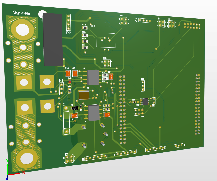
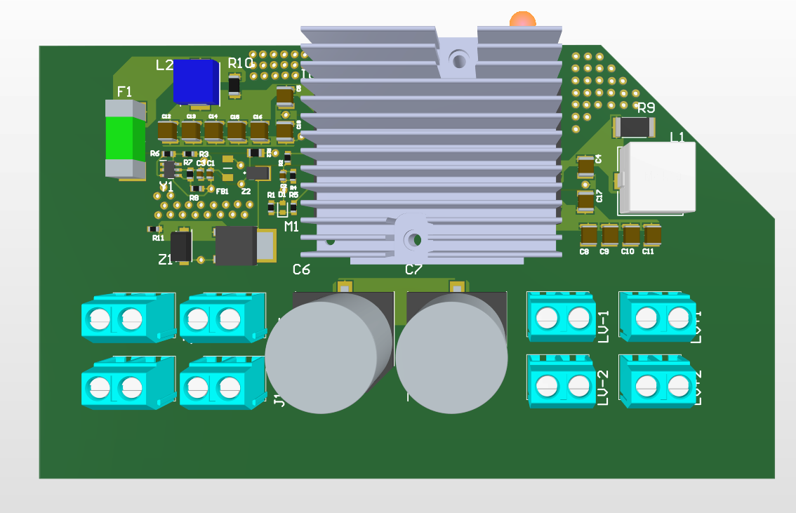
DCM
The output of bcm works as the input here and we use a DCM3623 dc-dc converter with input range of 16-50V and outputs a voltage of 24 V to form this PCB along with reverse polarity protection and filter circuits. Three PCBs are connected in parallel.
- Comments(2)
- Likes(2)


