


RP2040 Logic analyser shield for use with Scoppy and the MakerIOT2020 Raspberry Pi Pico Carrier board
An Easy RP2040 Logic Analyzer Shield - Scoppy Scope Part 2
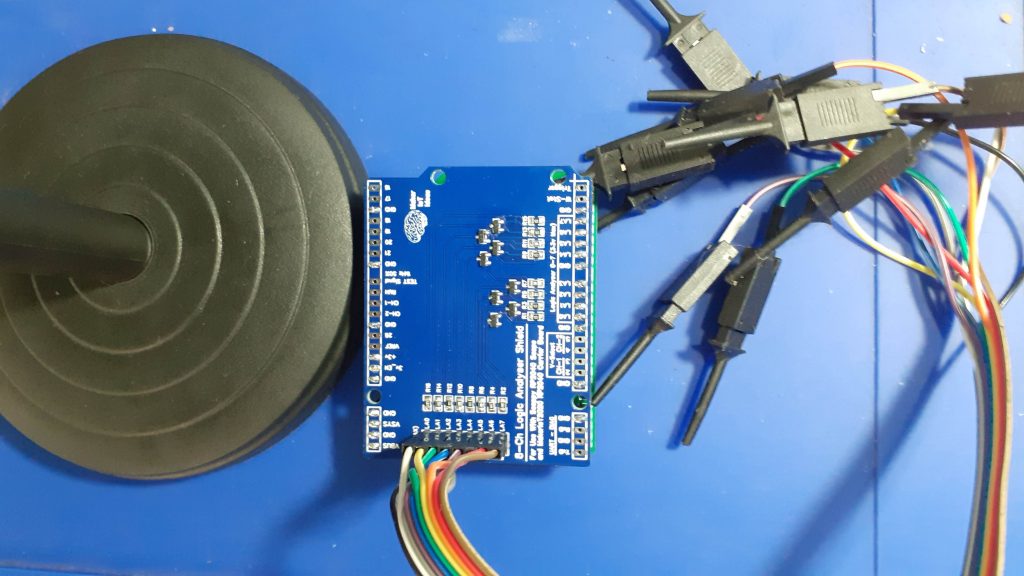
Scoppy Scope Logic analyser Shield with Logic Probes
As part two out of a series of three articles (part 1), This is the Scoppy RP2040 Logic analyzer shield, for use with our Raspberry Pi Pico Carrier board and the Scoppy Oscilloscope firmware for the RP2040.
In Part one, we took a very quick look at the installation of the firmware, as well as the basic limitations for use of this very useful project.
In this part, I want to take a quick look at my Logic Analyser shield, for use with this project, as well as the Raspberry Pi Pico Carrier Board. In part one, we saw that the logic analyzer inputs are limited to 3.3v by the RP2040 GPIO pins. This shield is a prototype attempt to overcome those limitations by using logic-level conversion.
What is on the PCB ?
The PCB is designed to be an add-on shield for the Makeriot2020 Raspberry Pi Pico Carrier Board. (Get your own here) It is in the same form factor as the Arduino Uno shields, but with pinputs specific to the RP2040 and Raspberry Pi Pico.
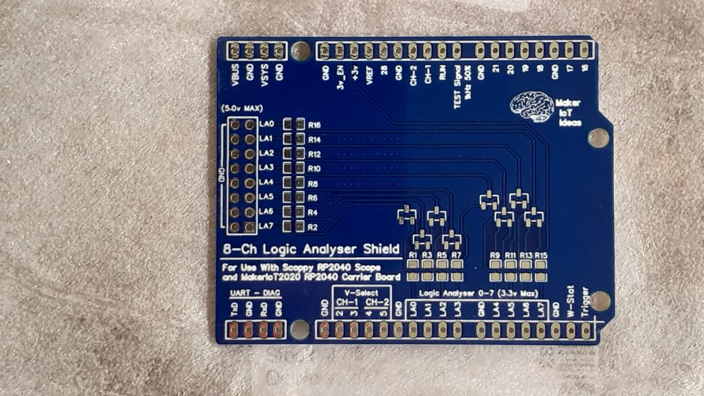
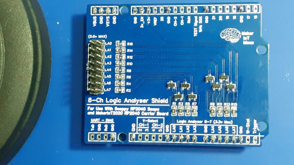
8 Ch Logic analyser Shield for use with Scoppy and MakerIOT2020 Pico Carrier Board
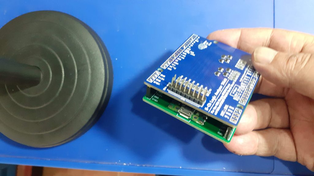
All Raspberry Pi Pico pins are broken out and labelled, as well as all of the pins specific to the Scoppy App have been clearly labelled. The board are stackable onto the Pico Carrier board, via standard 2.54mm Male Headers, or extra long, stackable female 2.45mm headers, similar to those found on common Arduino shields.
The use of stackable headers will allow simultaneous use of the logic analyser shield and the Analog frontend shield, introduced in part 3 of this series.
In addition to that, a 2x8-way 2.54mm Male header provides access to the 8 logic converted logic analyser inputs.
Logic conversion is done with a simple circuit, comprising a Bss138 N-Channel Mosfet and two 10K resistors per channel.
The shield is powered directly from the Pico Carrier board, which is in turn powered from the OTG cable to the Android Phone or tablet used to display the captured data. ( see Part 1 for installation instructions and other details regarding the Scoppy Project)
The logic level converters allow the use of a 5v logic signal, which is an improvement over the original design, which allowed only 3.3v inputs.
The Schematic and PCB Layout
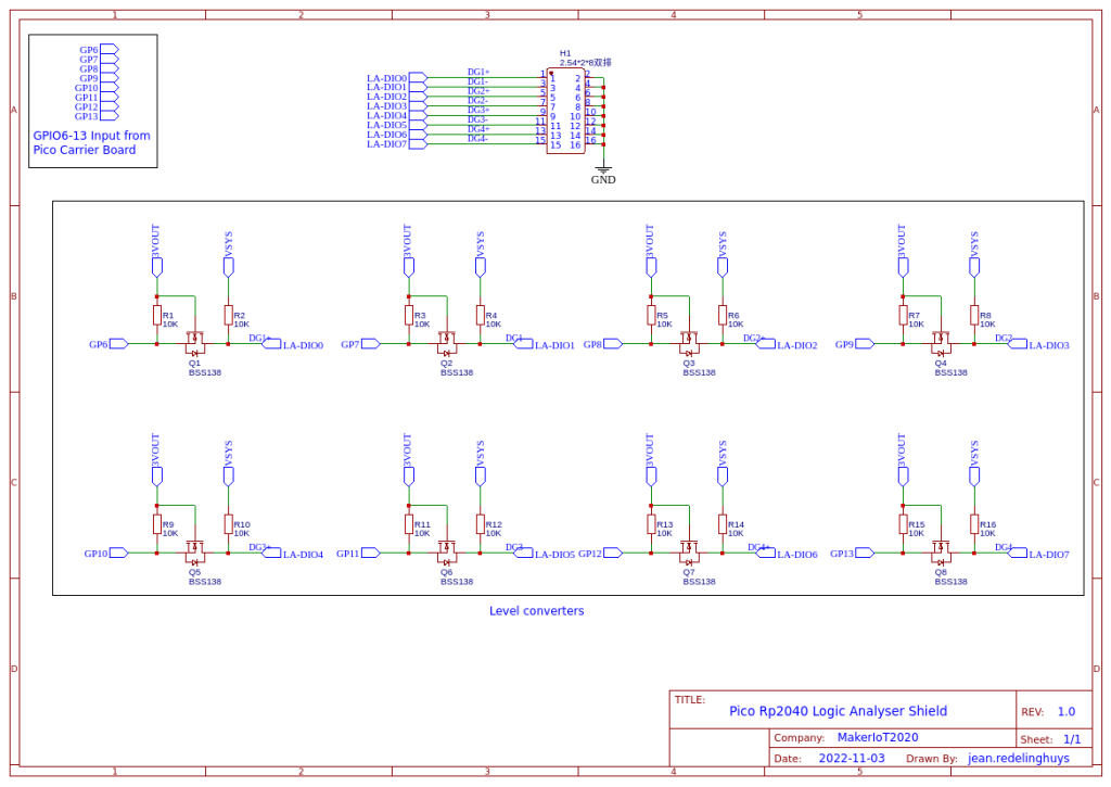
Logic analyser shield schematic
Schematic_Pico-Logic-Analyser-with-Level-Shifted-Inputs_2022-11-25-1
Download
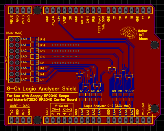
PCB Layout
Some more pictures of the device
Front
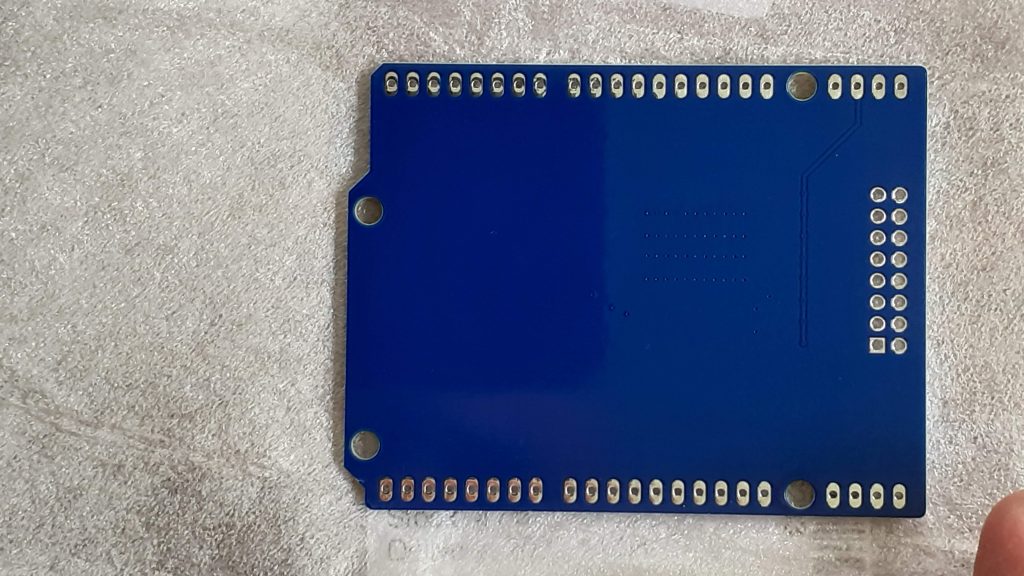 Back
Back
Assembled Front
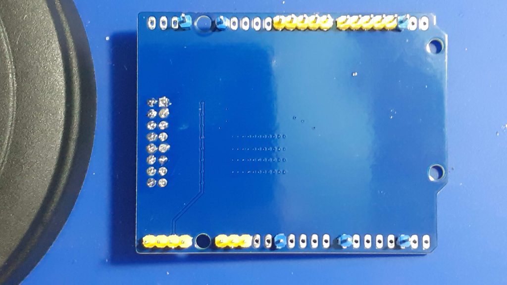 Assembled Back
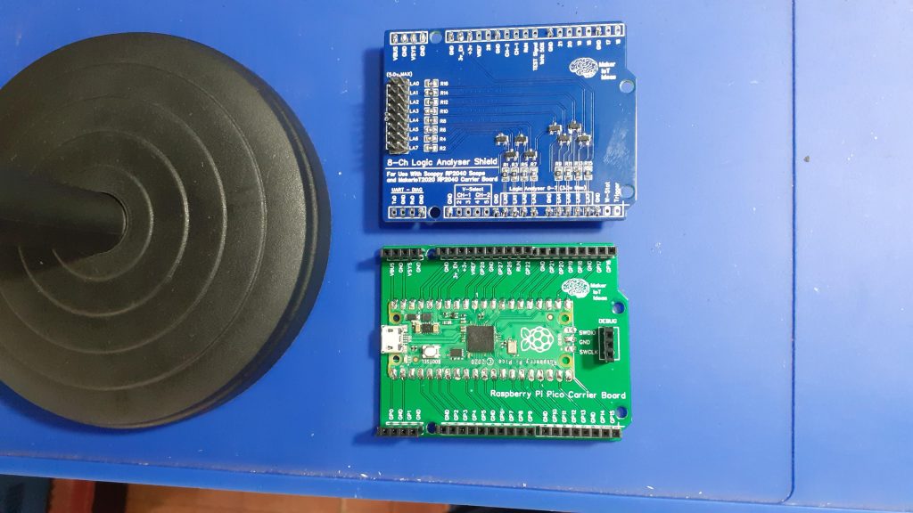 Logic analyser shield together with RP2040 carrier board
 Stacked view 1
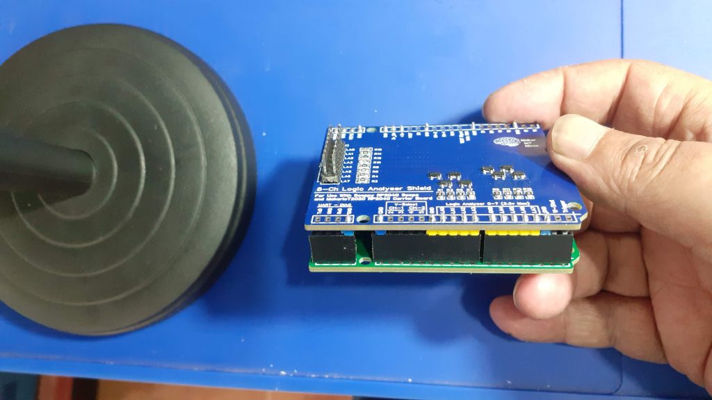 Stacked view 2
Stacked with logic probes
Installation instructions (repeated from Part 1)
All credits for the development of the Scoppy firmware goes to fhdm-dev. This shield is a modification made by MakerIOT2020, and thus belongs to me. In the spirit of the original project, It will however be released to the public as a free open-source project ( free as in free download, free schematic, free design ).

RP2040 Logic analyser shield for use with Scoppy and the MakerIOT2020 Raspberry Pi Pico Carrier board
*PCBWay community is a sharing platform. We are not responsible for any design issues and parameter issues (board thickness, surface finish, etc.) you choose.


Raspberry Pi 5 7 Inch Touch Screen IPS 1024x600 HD LCD HDMI-compatible Display for RPI 4B 3B+ OPI 5 AIDA64 PC Secondary Screen(Without Speaker)
BUY NOW


- Comments(0)
- Likes(3)
 More by Jean Redelinghuys MakerIoT2020
-
 PCB_MCP23008_2023-10-08
MCP23008 BreakoutI designed this breakout to assist me during prototyping my next version of the “RP...
PCB_MCP23008_2023-10-08
MCP23008 BreakoutI designed this breakout to assist me during prototyping my next version of the “RP...
-
 PCB_XiaoRP2040-Mouse-REV2
Xiao RP2040 Joystick Mouse – revision 2.00Revision 1.0 of the ProjectOver the last few months, I hav...
PCB_XiaoRP2040-Mouse-REV2
Xiao RP2040 Joystick Mouse – revision 2.00Revision 1.0 of the ProjectOver the last few months, I hav...
-
 Multi Purpose IO Card
Multi-Purpose IO CardWhen we are working on a prototype, we always need access to pushbuttons, encod...
Multi Purpose IO Card
Multi-Purpose IO CardWhen we are working on a prototype, we always need access to pushbuttons, encod...
-
 Variable Voltage Power Module
Powering electronics projects are always challenging. This Variable vol...
Variable Voltage Power Module
Variable Voltage Power ModulePowering electronics projects are always challenging. This Variable vol...
-
 I2C Matrix Keypad
An I2C Matrix KeypadThe completed I2C Matrix KeypadIn a previous post this month I introduced my 4×4...
I2C Matrix Keypad
An I2C Matrix KeypadThe completed I2C Matrix KeypadIn a previous post this month I introduced my 4×4...
-
 ESP32-S Development Board, in "Arduino Uno" form factor
UPDATE 24/06/2023:This board now has a Hardware Revision 2.0 available. It is the same board but wit...
ESP32-S Development Board, in "Arduino Uno" form factor
UPDATE 24/06/2023:This board now has a Hardware Revision 2.0 available. It is the same board but wit...
-
 W307186ASC94_Gerber_PCB_USB-Ports
USB Power Supply ModuleUSB Ports are quite handy to power all our day-to-day electronic devices, but...
W307186ASC94_Gerber_PCB_USB-Ports
USB Power Supply ModuleUSB Ports are quite handy to power all our day-to-day electronic devices, but...
-
 Atmega 328P based PWM controller Card
ATMega 328P Based PWM controller CardAs part of my recent ESP-12E I2C Base Board project, I designed...
Atmega 328P based PWM controller Card
ATMega 328P Based PWM controller CardAs part of my recent ESP-12E I2C Base Board project, I designed...
-
 W307186ASC71_Gerber_PCB_ESP-Now Remote
Today we will look at the remote control unit for the Robotic Toy Car – Part 6.The project is close ...
W307186ASC71_Gerber_PCB_ESP-Now Remote
Today we will look at the remote control unit for the Robotic Toy Car – Part 6.The project is close ...
-
 W307186ASV69_Gerber_PCB_Robot-Car-MCU-Board Prototype
In our last project, we started working on repurposing an old toy car. In this part, Robot Toy Car –...
W307186ASV69_Gerber_PCB_Robot-Car-MCU-Board Prototype
In our last project, we started working on repurposing an old toy car. In this part, Robot Toy Car –...
-
 W307186ASV62_Gerber_PCB_DUAL-H-Bridge
by makeriot2020 on May 27, 2022Many of us have old toys laying around the house, they belong to ou...
W307186ASV62_Gerber_PCB_DUAL-H-Bridge
by makeriot2020 on May 27, 2022Many of us have old toys laying around the house, they belong to ou...
-
 CAN-BUS Breakout
Breadboard Compatible CAN-BUS Breakout ModuleWhat is this:Some of us have already used the commonly ...
CAN-BUS Breakout
Breadboard Compatible CAN-BUS Breakout ModuleWhat is this:Some of us have already used the commonly ...
-
 RA-02 Breakout with Level converters
Breadboard and beginner-friendly RA-02 Breakout ModuleMost Makers and electronics enthusiasts may al...
RA-02 Breakout with Level converters
Breadboard and beginner-friendly RA-02 Breakout ModuleMost Makers and electronics enthusiasts may al...
-
 ATMEGA328P Module with integrated LoRa and CAN Bus
ATMEGA328P Module with integrated LoRa and CAN-BUSINTRODUCTIONIn my quest to perfect my LoRa telemet...
ATMEGA328P Module with integrated LoRa and CAN Bus
ATMEGA328P Module with integrated LoRa and CAN-BUSINTRODUCTIONIn my quest to perfect my LoRa telemet...
-
 Sx127x-Ra-02-Test-Module with ATMEGA328P-AU
SX127x LoRa/FSK/OOK Prototype Radio BoardI recently had a requirement to do some automation/telemetr...
Sx127x-Ra-02-Test-Module with ATMEGA328P-AU
SX127x LoRa/FSK/OOK Prototype Radio BoardI recently had a requirement to do some automation/telemetr...
-
 USB-ASP Programmer ATMEGA8
Build your own USB-ASP Programmer CloneBymakeriot2020 FEB 21, 2022 Arduino, ASP programmerUsing mor...
USB-ASP Programmer ATMEGA8
Build your own USB-ASP Programmer CloneBymakeriot2020 FEB 21, 2022 Arduino, ASP programmerUsing mor...
-
 ATTiny1616-LIGHT-Controller-with-CAN_B_PCB_ATTiny1616-LIGHT-Controller-with-C_2024-09-11
Assembly of the ATTiny1616 Can bus controller PCBThe Assembly of the ATTiny1616 Can Bus Controller P...
ATTiny1616-LIGHT-Controller-with-CAN_B_PCB_ATTiny1616-LIGHT-Controller-with-C_2024-09-11
Assembly of the ATTiny1616 Can bus controller PCBThe Assembly of the ATTiny1616 Can Bus Controller P...
-
 ATTiny1616QFN-CAN-Remote-Neopixel-Ligh_PCB_ATTiny1616QFN-CAN-Remote-Neopixel-2024-09-11_2024-09-11
NeoPixel CAN-Bus Module with local controlAs part of my current project to add NeoPixels to the cabi...
ATTiny1616QFN-CAN-Remote-Neopixel-Ligh_PCB_ATTiny1616QFN-CAN-Remote-Neopixel-2024-09-11_2024-09-11
NeoPixel CAN-Bus Module with local controlAs part of my current project to add NeoPixels to the cabi...
-
-
ARPS-2 – Arduino-Compatible Robot Project Shield for Arduino UNO
1280 0 4 -
A Compact Charging Breakout Board For Waveshare ESP32-C3
1795 3 7 -
AI-driven LoRa & LLM-enabled Kiosk & Food Delivery System
1782 2 0 -
-
-
-
ESP32-C3 BLE Keyboard - Battery Powered with USB-C Charging
1962 0 1 -


