PCBWay Community
Search title or content
Search
PCBWay
PCB Instant Quote
CNC | 3D Printing
Login
Sign Up
More Notifications
No notifications.
My Profile
My projects
My Likes
My Deals
My Goods for Bazaar
Settings
Sign Out
Projects
Categories
DIY Electronics
Arduino
Hardware
Audio
Computers & USB
Breakout Board Projects
Home Automation
LED Displays & Matrices
IoT
Robotics
View all categories
By Source Files
Onju Voice - AI assistant replacement to Google Nest Mini by @justLV
LogicAnalyzer V6.0
DIY 1kW Open Source MPPT Solar Charge Controller
Tad Boy Color
SummerCart64 - a fully open source N64 flashcart
kv4p HT v1.7b
QuinLED-Dig-Uno
Bike Fingerprint - PCB
Arduino RC engine sound & light controller with inertia simulation for ESP32
Solar Powered WiFi Weather Station V2.0
Frog Boy Color
SIDKick pico 0.2 (SID 6581/8580-replacement for C64/C128)
View all source files projects
Featured Projects
Onju Voice - AI assistant replacement to Google Nest Mini by @justLV
LogicAnalyzer V6.0
DIY 1kW Open Source MPPT Solar Charge Controller
Featured
Source Files
Video
View all projects
Questions
Sponsorships
Feedback
Blog
Store
PCB Design
Contest
- 2026 KiCad PCB Design Contest
- 8th Project Design Contest
- 7th Project Design Contest
- KiCad Design Contest
- 6th Project Design Contest
- 5th PCB Design Contest
- 4th PCB Design Contest
- Raspberry Pi Pico Contest
- PCB Design Tutorial
- 3rd PCB Design Contest
- I CAN SOLDER Kit Contest
- 2nd PCB Design Contest
- 1st PCB Design Contest
Add questions
Create a project
Please verify your email address so that you can enjoy our more comprehensive services.
Wearables
Weather
All categories
DIY Electronics
Arduino
Hardware
Audio
Computers & USB
Breakout Board Projects
Home Automation
LED Displays & Matrices
IoT
Robotics
3D Printing
Blinkenlights
Calculator
Camera
Clocks
CNC
Educational
Automotive
Electronic Games
ESP32
Fabrication Tools
Flight
Guitar
Keyboards
Misc
Music
Nixie Tube
Oscilloscope
Particle
Power Supply
Programmable Logic Projects
Raspberry Pi
Radio
Retro Stuffs
Space & Satellite
Sensors
Software
Synthesizer
Ultrasonic
Virtual Reality
Wearables
Weather
Project by top creative fields
All categories
3D Printing
Arduino
Audio
Automotive
Blinkenlights
Breakout Board Projects
Calculator
Camera
Clocks
CNC
Computers & USB
DIY Electronics
Educational
Electronic Games
ESP32
Fabrication Tools
Flight
Guitar
Hardware
Home Automation
IoT
Keyboards
LED Displays & Matrices
Misc
Music
Nixie Tube
Oscilloscope
Particle
Power Supply
Programmable Logic Projects
Radio
Raspberry Pi
Retro Stuffs
Robotics
Sensors
Software
Space & Satellite
Synthesizer
Ultrasonic
Virtual Reality
Wearables
Weather
View all categories
Breakout Board Projects
Breakout boards take small sensors, chips and components and make them easy to use with your Raspberry Pi, Metro, Feather, Arduino or whatever platform you like most!
All tags
Board
Development Board
Module
USB
Breakout
Battery
Create a project
Sort by : Trending
Trending
Score
Likes
Views
Discuss
Newest
Featured
Source Files
3D Design
Video
USB-C / USB-A Breakout BoardMultipurpose Breakout board for USB-C & USB-A. Compact form factor with improved practicality and usability.Features:USB-C FemaleUSB-A Male (PCB Edge)Reverse Current pr...
USB-A / USB-C Breakout Board
4482
9
5
Muhammad Aitesam
Muhammad Aitesam
PAKISTAN
26
8
USB-Serial ProgrammerIn IOT world, we have to deal with embedded electronics and IoT projects where USB-Serial Programmers are required. SOmetimes they are embedded On the board while sometimes it req...
CP2102 Based USB_Serial Programmer
2556
0
2
Muhammad Aitesam
Muhammad Aitesam
PAKISTAN
26
8
18650 2S2P Battery Charger and ProtectionThis product was designed as a breakout power board for portable projects. I'm currently working a few medium sized projects which needed a reliable battery po...
18650 2S2P Battery Charger, Protection and 5V Output Board
4068
1
10
Chris Haynes
Chris Haynes
UNITED KINGDOM
7
0
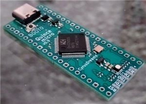
IntroductionThe 10-cent-microcontroller, it was everywhere in the news. With a 32bit RISC-V core and useful peripherals, the CH32V003 from WCH is suited to many projects. But such a small microcontrol...
Quince micro lite
611
1
1
Cyrus Dreams
Cyrus Dreams
GERMANY
0
0
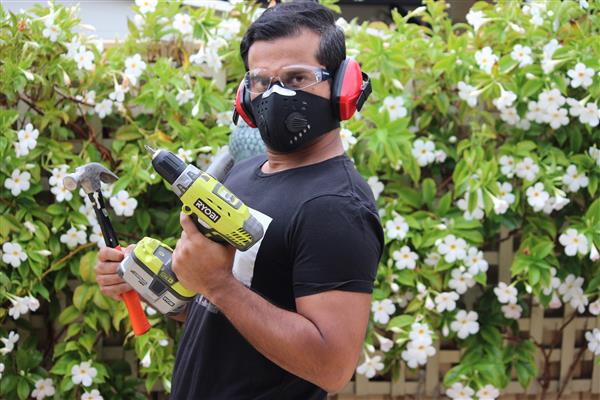
Top 10 Arduino projects for beginners to advance in 2022. You may find them helpful for your school's science project or for some cool DIY stuff which you can make using Arduino.Disclaimer: Most ...
Top 10 Arduino Projects
4227
0
2
Ashish Adhikari
Ashish Adhikari
AUSTRALIA
34
6
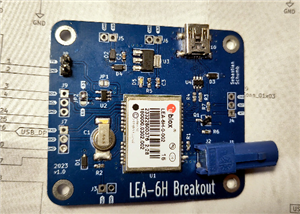
A versatile breakout board for the U-blox LEA6-H module.This breakout board exposes all the interfaces of the GPS-module:USB self-powered or bus-powered3.3v UARTI2CPPS signal out with a buffer/levelsh...
LEA-6H Breakout
403
3
0
Sebastian S.
Sebastian S.
GERMANY
0
0
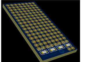
The Prototype Board (100x100mm, 2.54mm pitch) is a general-purpose PCB designed for prototyping electronic circuits. It provides a grid of plated through-holes spaced at a standard 2.54...
Prototype Board, 2.54mm, 100x100mm
873
0
0
Vigus UA
Vigus UA
UKRAINE
0
0
This is a very complicated design for A perfboard that I made A long time ago, I hope You Enjoy it!
Diy PCB Perfboard
375
0
1
. Real Space Pro
. Real Space Pro
UNITED ARAB EMIRATES
2
0
STM32 Explorer Board - STM32XP This is an educational development board conceived as part of a PCB Design course. The course is offered via Portal Embarcados website (Course Page). The hard...
STM32 Explorer Board - STM32XP
2771
5
2
André Araújo
André Araújo
BRAZIL
2
0
What?This is handy development board with CH551G, USB-C jack and all the required extra components. Board has small prototyping/perboard area where user can solder their prototype circuits. That micro...
CH551G Prototyping Board W/USB-C
2083
0
2
HackVlog Hugatry
HackVlog Hugatry
FINLAND
6
0
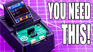
https://youtu.be/NPpPVw-4qi8For the most information, the CODE and more, check out the website article:https://simpleelectronics.ca/an-i2c-address-scanner-for-your-desk/The long and the short is that ...
RP2040 i2c Scanner
2515
0
12
Simple Electronics
Simple Electronics
CANADA
33
0
The heart of the circuit consists of the integrated MCP2221A produced by Microchip . This integrated is cataloged as USB 2.0 to I2C / UART Protocol Conv...
UART+I2C USB Bridge
5525
0
3
Giovanni CyB3rn0id at Settorezero.com
Giovanni CyB3rn0id at Settorezero.com
ITALY
18
19
Small breakout board based on STM32F070 microcontroller from ST Microelectronics.With this board one can easily prototype small ARM Cortex M0 applications with minimum effort and expense. It can ...
STM32F070 Breakout
3650
4
3
Dario Murgia
Dario Murgia
ITALY
58
20
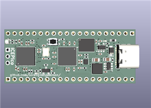
iCEPico========A compact development board combining the RP2350 microcontroller and the ICE40UP5K-SG48I FPGA in a Raspberry Pi Pico form factor.OVERVIEW--------The iCEPico is a custom PCB that pairs t...
iCEPico - A RP Pico 2 Inspired FPGA Dev Board
297
0
3
Engineer
Engineer
UNITED STATES OF AMERICA
0
0
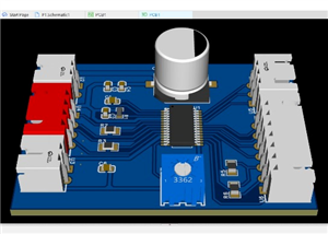
OverviewThis project is a custom-designed DRV8825 stepper motor driver PCB intended for robotics, automation, and embedded motion control applications. The board is designed as a reliable and compact ...
DRV8825 Stepper Driver
525
0
2
Danu Rahmat Alfiyan
Danu Rahmat Alfiyan
INDONESIA
0
0
In today's world, electronics projects often require the integration of multiple sensors to collect and process data for various applications. The custom breakout board we've designed serves as a vers...
Ambient Sensors Breakout Board
1718
0
1
Inaki Iturriaga
Inaki Iturriaga
ARGENTINA
5
0
1
2
3