


ARDUINO PWM SOLAR CHARGE CONTROLLER ( V 2.02)
If you are planning to install an off-grid solar system with a battery bank, you’ll need a Solar Charge Controller. It is a device that is placed between the Solar Panel and the Battery Bank to control the amount of electric energy produced by Solar panels going into the batteries. The main function is to make sure that the battery is properly charged and protected from overcharging.
As the input voltage from the solar panel rises, the charge controller regulates the charge to the batteries preventing any overcharging and disconnect the load when the battery is discharged.
Types of solar charge controllers
There are currently two types of charge controllers commonly used in PV power systems :
1. Pulse Width Modulation (PWM) controller
2. Maximum Power Point Tracking (MPPT) controller
In this tutorial, I will explain to you about the PWM Solar Charge Controller.
Specification
1.Charge controller as well as energy meter
2. Automatic Battery Voltage Selection (6V/12V)
3. PWM charging algorithm with auto charge set point according to the battery voltage
4.LED indication for the state of charge and load status
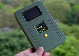
5. 20x4 character LCD display for displaying voltages, current, power, energy, and temperature.
6.Lightning protection
7.Reverse current flow protection
8.Short Circuit and Overload protection
9. Temperature Compensation for Charging
10. USB port for Charging Gadgets
Build Instruction
Instructables : https://www.instructables.com/id/ARDUINO-PWM-SOLAR-CHARGE-CONTROLLER-V-202/
My Website: https://www.opengreenenergy.com/post/arduino-pwm-solar-charge-controller-v-2-02
How the Circuit Works ?

Note : Red Line - Power and Yellow Line - Control Signal

The heart of the charge controller is an Arduino Nano board. The Arduino senses the solar panel and battery voltages by using two voltage divider circuits. According to these voltage levels, it decides how to charge the battery and control the load.
Note : In the above picture, there is typographical error in power and control signal. The red line is for power and yellow line is for control signal.
The whole schematic is divided into the following circuits:
1. Power Distribution Circuit:
The power from the battery ( B+ & B- ) is step down to 5V by the X1 ( MP2307) buck converter. The output from the buck converter is distributed to
1. Arduino Board
2. LEDs for indication
3. LCD display
4. USB port to charge gadgets.
2. Input Sensors:
The solar panel and battery voltages are sensed by using two voltage divider circuits consisting of resistors R1-R2 & R3- R4. C1 and C2 are filter capacitors to filter out the unwanted noise signals. The output from the voltage dividers is connected to Arduino analog pins A0 and A1 respectively.
The solar panel and battery currents are sensed by using two ACS712 modules. The output from the current sensors is connected to Arduino analog pin A3 and A2 respectively.
The battery temperature is measured by using a DS18B20 temperature sensor. R16 (4.7K ) is a pull-up resistor. The output of the temperature sensor is connected to Arduino Digital pin D12.
3. Control Circuits:
The control circuits are basically formed by two p-MOSFETs Q1 and Q2. The MOSFET Q1 is used to send the charging pulse to the battery and MOSFET Q2 is used to drive the load. Two MOSFET driver circuits are consist of two transistors T1 and T2 with pull-up resistors R6 and R8. The base current of the transistors is controlled by resistors R5 and R7.
4. Protections Circuits:
The input over voltage from the solar panel side is protected by using a TVS diode D1. The reverse current from the battery to the solar panel is protected by a Schottky diode D2. The over current is protected by a fuse F1.
5. LED Indication:
LED1, LED2, and LED3 are used to indicate solar, battery and load status respectively. Resistors R9 to R15 are current limiting resistors.
7. LCD Display:
An I2C LCD display is used to display various parameters.
8. USB Charging:
The USB socket is hooked up to 5V output from the Buck Converter.
9. System Reset:
SW1 is a push button to reset the Arduino.
ARDUINO PWM SOLAR CHARGE CONTROLLER ( V 2.02)
*PCBWay community is a sharing platform. We are not responsible for any design issues and parameter issues (board thickness, surface finish, etc.) you choose.


Raspberry Pi 5 7 Inch Touch Screen IPS 1024x600 HD LCD HDMI-compatible Display for RPI 4B 3B+ OPI 5 AIDA64 PC Secondary Screen(Without Speaker)
BUY NOW


- Comments(17)
- Likes(45)
- 28 USER VOTES
- YOUR VOTE 0.00 0.00

-
5design
-
5usability
-
6creativity
-
7content
-
10design
-
10usability
-
10creativity
-
10content
-
10design
-
10usability
-
10creativity
-
10content
-
9design
-
10usability
-
9creativity
-
10content
-
10design
-
10usability
-
10creativity
-
10content

-
10design
-
10usability
-
10creativity
-
10content
-
5design
-
1usability
-
9creativity
-
10content

-
8design
-
10usability
-
9creativity
-
10content
-
10design
-
10usability
-
10creativity
-
10content
-
7design
-
7usability
-
6creativity
-
6content
-
8design
-
8usability
-
10creativity
-
8content
-
1design
-
2usability
-
3creativity
-
4content
-
1design
-
2usability
-
3creativity
-
5content
-
10design
-
10usability
-
10creativity
-
10content
-
10design
-
10usability
-
10creativity
-
10content
-
8design
-
9usability
-
8creativity
-
7content
-
9design
-
10usability
-
5creativity
-
8content
-
9design
-
9usability
-
9creativity
-
9content
-
1design
-
2usability
-
3creativity
-
4content

-
7design
-
8usability
-
7creativity
-
9content
-
10design
-
10usability
-
10creativity
-
10content

-
8design
-
8usability
-
8creativity
-
7content

-
8design
-
10usability
-
8creativity
-
9content

-
8design
-
8usability
-
8creativity
-
9content

-
9design
-
10usability
-
10creativity
-
9content
-
10design
-
10usability
-
10creativity
-
10content
-
10design
-
10usability
-
10creativity
-
10content
-
10design
-
10usability
-
10creativity
-
8content
More by Open Green Energy
-
 DIY Smart Multipurpose Battery Tester
In recent years, the market has been flooded with low-cost batteries, many of which originate from u...
DIY Smart Multipurpose Battery Tester
In recent years, the market has been flooded with low-cost batteries, many of which originate from u...
-
 Solar Powered WiFi Weather Station V4.0
This is an affordable weather station for various applications like smart agriculture, smart city, s...
Solar Powered WiFi Weather Station V4.0
This is an affordable weather station for various applications like smart agriculture, smart city, s...
-
 DIY Solar Bottle Lamp V1.0
Solar Bottle Lamp is a solar-powered light that is constructed from waste plastic bottles. The desig...
DIY Solar Bottle Lamp V1.0
Solar Bottle Lamp is a solar-powered light that is constructed from waste plastic bottles. The desig...
-
 https://www.instructables.com/DIY-Solar-Power-Meter/
Accurate measurement of solar irradiance is one of the most critical steps in solar photovoltaic sys...
https://www.instructables.com/DIY-Solar-Power-Meter/
Accurate measurement of solar irradiance is one of the most critical steps in solar photovoltaic sys...
-
 DIY Solar Mason Jar Lamp
Making a solar mason Jar Lamp is not just a fun project; it’s also a fantastic way to learn about re...
DIY Solar Mason Jar Lamp
Making a solar mason Jar Lamp is not just a fun project; it’s also a fantastic way to learn about re...
-
 LED PCB for DIY Solar Bottle Lamp V2.0
DIY Solar Bottle Lamp V2.0 contains two PCBs, one is the Main PCB and the other is the LED PCB.This ...
LED PCB for DIY Solar Bottle Lamp V2.0
DIY Solar Bottle Lamp V2.0 contains two PCBs, one is the Main PCB and the other is the LED PCB.This ...
-
 DIY Portable Solar Generator V2
A DIY portable solar generator is an excellent project for individuals who want to harness the power...
DIY Portable Solar Generator V2
A DIY portable solar generator is an excellent project for individuals who want to harness the power...
-
 DIY 18650 Power Bank With Flashlight
BOM :Powerbank Module: https://s.click.aliexpress.com/e/_DBELYV918650 Battery: https://s.click.aliex...
DIY 18650 Power Bank With Flashlight
BOM :Powerbank Module: https://s.click.aliexpress.com/e/_DBELYV918650 Battery: https://s.click.aliex...
-
 Solar WiFi Weather Station V4 Receiver ( Rx )
Note:One more important thing, both the transmitter and receiver board must be in the same frequency...
Solar WiFi Weather Station V4 Receiver ( Rx )
Note:One more important thing, both the transmitter and receiver board must be in the same frequency...
-
 DIY Solar Panel Monitoring System – V2.0
As solar photovoltaic (PV) systems become increasingly popular as a clean and renewable source of en...
DIY Solar Panel Monitoring System – V2.0
As solar photovoltaic (PV) systems become increasingly popular as a clean and renewable source of en...
-
 Main PCB for DIY Solar Bottle Lamp V2.0
PCBWay Note: DIY Solar Bottle Lamp V2.0 contains two PCBs, one is the Main PCB and the other is the ...
Main PCB for DIY Solar Bottle Lamp V2.0
PCBWay Note: DIY Solar Bottle Lamp V2.0 contains two PCBs, one is the Main PCB and the other is the ...
-
 How to Make a 12V Lead Acid Battery Charger with CC & CV
I made a simple battery charger for charging my 12V/7Ah SLA battery commonly used inside the UPS for...
How to Make a 12V Lead Acid Battery Charger with CC & CV
I made a simple battery charger for charging my 12V/7Ah SLA battery commonly used inside the UPS for...
-
 TP4056 Based Solar Bottle Lamp
Solar Bottle Lamp is a solar-powered light that is constructed from waste plastic bottles. The desig...
TP4056 Based Solar Bottle Lamp
Solar Bottle Lamp is a solar-powered light that is constructed from waste plastic bottles. The desig...
-
 DIY Mini UPS for WiFi Router V5.0
The pandemic COVID-19 outbreak forced companies to continue with work-from-home policy to maintain s...
DIY Mini UPS for WiFi Router V5.0
The pandemic COVID-19 outbreak forced companies to continue with work-from-home policy to maintain s...
-
 ESP8266 Weather Widget V2.0
Welcome to my new Weather Widget Project. Earlier I have posted an article on the weather widget, th...
ESP8266 Weather Widget V2.0
Welcome to my new Weather Widget Project. Earlier I have posted an article on the weather widget, th...
-
 DIY Non Contact IR Thermometer V1.0
Currently, we are chasing an invisible monster named Corona Virus ( COVID-19 ) and we are going thro...
DIY Non Contact IR Thermometer V1.0
Currently, we are chasing an invisible monster named Corona Virus ( COVID-19 ) and we are going thro...
-
 Solar Powered WiFi Weather Station V3.0
Note: now the version is 3.2 This Weather Station is such compact weather station that consists of s...
Solar Powered WiFi Weather Station V3.0
Note: now the version is 3.2 This Weather Station is such compact weather station that consists of s...
-
 DIY Emergency Light
Features:● Long Battery Backup ( 6V / 4.5Ah )● Light can bе соnnесtеd tо the power source аll t?mе.●...
DIY Emergency Light
Features:● Long Battery Backup ( 6V / 4.5Ah )● Light can bе соnnесtеd tо the power source аll t?mе.●...
-
Programmable Mist Maker - XIAO / QT PY Extension
450 0 0 -
RadioHAT - Raspberry Pi radio development platform
354 0 1 -
-
-
-
-
ARPS-2 – Arduino-Compatible Robot Project Shield for Arduino UNO
2899 0 6 -
A Compact Charging Breakout Board For Waveshare ESP32-C3
3402 3 8 -
AI-driven LoRa & LLM-enabled Kiosk & Food Delivery System
3726 2 2


