Summary: This article discusses the single-phase full-converter operations, its waveform, circuit diagrams, RLE average voltage, resistor loads, and output RMS expression_s. We shall end the discussion by enlightening our readers on the single-phase full-converter inverter operation mode.
Previously, we had a look at the single-phase semi-converter design. We noted that the converter utilizes the technology of two thyristors and two diodes in its bridge circuit supported by a flywheel diode connected across a resistor-inductor-emf series connection. In this article, our focus shifts to the design of a single-phase full-converter. This type of converter utilizes a bridge circuit made purely of thyristors to convert alternating signal input to direct signal output. Due to the utilization of the silicon-controlled rectifiers only in its circuitry, the converter is wholly owned, and the advantage of this is that it offers a more significant margin of control over the output signal levels.
Circuit Diagram of the Single-Phase Full-Converter connected to the RLE load
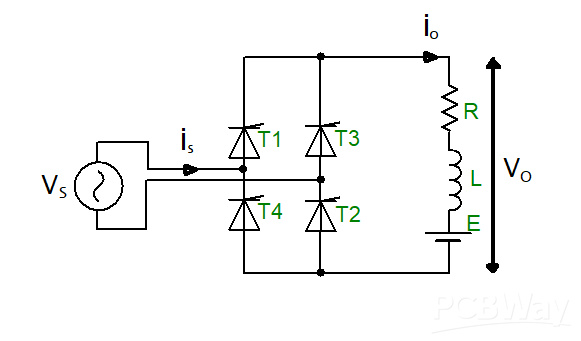
Figure 1:Circuit Diagram of the Single-Phase Full-Converter connected to the RLE load
The circuit utilizes T1, T2, T3, and T4 thyristors. The load connected to the converter is an RLE load type where L stands for an inductor, R stands for a resistor, and E represents the emf load, which might be from a connected battery source or maybe due to the DC motor back emf.
The convert works following a principle of triggering two thyristors at once. In the circuit, thyristors T1 and T2 are activated simultaneously, and after a period that is π radian, the thyristor par of T3 and T4 are also simultaneously triggered. The operation is continuous. Since a load is connected to the converter circuit, the load is assumed to be in a constant mode.
Single-Phase Full-Converter Waveforms
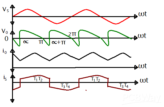
Figure 2:Single-Phase Full-Converter Waveforms
The figure above is representative of the single-phase full-converter connected to an RLE load. The current i0 represents the load current, which is in continuous mode.
In the period between ωt = 0 and ωt=α, thyristors T1 and T2 operate in the forward-biased mode. At the same period, T3 and T4 are in the conducting method.
At the period ωt = α, the T1 and T2 SCRs are triggered and conducted. The two thyristors are in conduction mode. At the instant when thyristors T1 and T2 begin to work, there is an appearance of Vm sin α voltage across thyristors T3 and T4. This voltage is in reverse bias mode. The turning on of T3 and T4 is known as a line or natural commutation. At this point, the current of the load, i0, is transferred from thyristors T3 and T4 to thyristors T1 and T2.
Thyristors T1 and T2 can only be turned on when Vm sin α > E. At this mode of operation, thyristors T1 and T2 are in conduction mode for a period of π radian that is at the range ωt=α to ωt=π+α.
At ωt=π+α, thyristors T3 and T4 are forward-biased. At this point, the two thyristors get triggered, as thyristors T1 and T2 are turned off by line or natural commutation. The load current is now transferred from thyristors T1 and T2 to thyristors T3 and T4, and this triggers thyristors T3 and T4 to be in conduction mode for a period of π radian that is at the range ωt=π+α to ωt=2π+α.
Voltage, Power, and Current Flow
Across the thyristors occurs maximum reverse voltage labeled as Vm. During the interval of 0 to α, the voltage from the supply VS is positive, while the current from the collection is positive. This makes some energy from the load return to the power supply.
During the interval period α to π, the system’s supply current and voltage are positive. This makes the power supplied positive and, thus, is the supply load source. From the discussion above, we can note that sometimes, power flows from the source towards the load start; other times, the power flows from the lower energy towards the load. We cannot forget to state that the net power flows toward the point in the power supply as the positive power duration is greater than the negative power duration, which is α to π more significant than 0 to α.
Average and RMS output DC Voltage
The average DC output voltage equation can be discussed as follows;
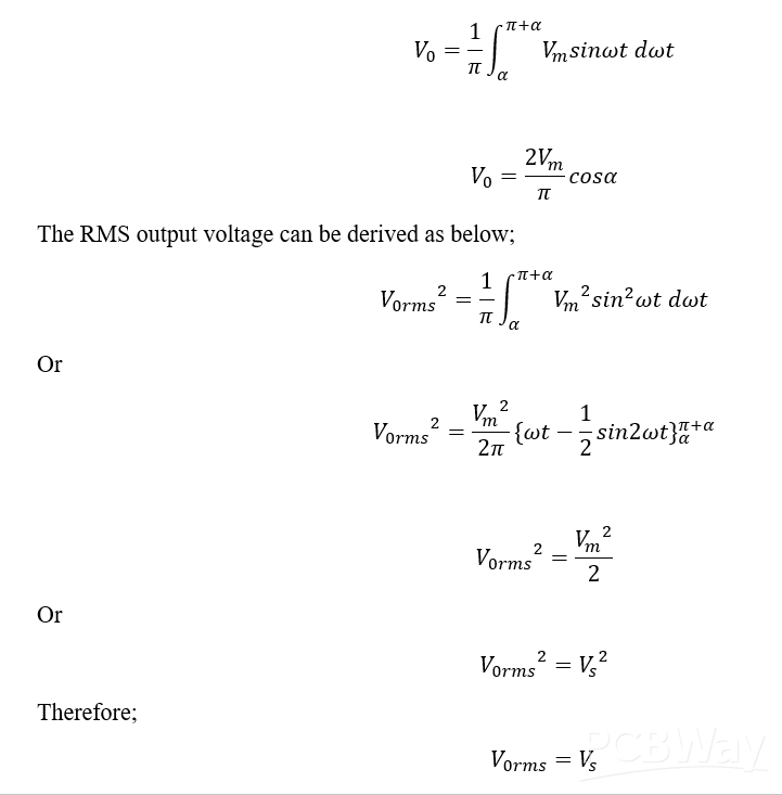
In this type of converter, the RMS output voltage is equal to the source voltage.
When the converter firing angle exceeds 90 degrees, it starts operating in inverter mode with a negative output voltage.
The EMF is reversed to supply power back to the circuit source. This type of operation makes the converter behave like an inverter, commonly called the Line-commutated inverter.
Inverter Operation Mode Waveform
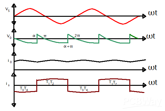
Figure 3:Inverter Operation Mode Waveform
From the graph above, the source voltage (VS) is positive for 0 to α, and the source current(IS) is negative. This tells us that power flows towards the AC source from the load emf, E. From interval α to π, both the supply current and voltage are positive; hence, the power flows towards the load circuit from the AC source.
For the converter of the Single-Phase Full circuit, the turn-off time is derived from the equation;

In summary


