Summary: This article describes a designing process by using a method of for stages; Specify, Design, Create and Validate. These stages cover all necessary steps in the design process.
The Four Stages of Design
Ing. Mark Donners
‘Since new developments are the product of a creative mind, we must therefore stimulate and encourage that type of mind in every way possible’
George Washington Carver
USED WITH PERMISSION BY AUTHOR & Publisher (me) for publication on the website of PCBWAY.COM
Copyright © 2016 by Mark Donners
This article is part of my book called: “Embedded Systems Design”
First print: December 2016
ISBN 978-1-326-88646-2
Published by Mark Donners
Mark.Donners@judoles.nl
www.theelectronicengineer.nl
Ordering Information:
This book can be ordered at www.lulu.com. Also, you might want to check out your local or online bookstore.
-------
The need to validate
Before getting into details about the different design methods, one should remember the bigger picture. What exactly is the process of designing? Irrespective of the design method, the purpose is always the same: to transform an idea into a product or solution well guided by the demands, wishes and specifications.

To transform an idea into a product, one has to work out the design of the actual product. To be able to design a product, one should first establish what it is to achieve and under what circumstances. This can be done by recording and documenting the demands and wishes that the customer has for this product. As a designer, it is in everyone’s interest to take part in making this inventory of specifications. The designer should take part interactively because a customer does not always put in words what he really wants. He might ask for an atomic accelerator but what he really wants is a centrifuge to dry his laundry. This might sound silly but do not forget; a customer often has no specific knowledge about how things can be done. He simply has a brilliant idea.
A good designer always thinks side by side with the customer. Together, both the designer and the customer try to find a working solution. Only after the specifications are clearly documented, the designer can start with the actual process of designing. It is possible to classify the different sorts of specification. For instance: product specifications and user specifications. However, it is more important to establish which specifications are critical and which are optional. In the end, the product should meet all the critical specifications and some (or all) of the optional specifications.
Sometime it is necessary to meet each other half way in order to complete the design. This could mean that some specifications are not met. A design is only successful if both the designer and the customer are pleased in the end.
To check if the critical and optional specifications are met, the product has to be validated before it is officially handed over to the customer. Unfortunately, the validation of the specifications as agreed upon earlier in the process of designing is often forgotten. Within the enthusiasm of designing, it is so easy to get lost in a direction without noticing the side track you could be on.
It is therefore most important to keep track of your specifications throughout every step of the process and evaluating the final design against these specifications is always necessary.

If during the design, the designer finds out that the design is off track with the specifications, it is necessary to (partly) redesign. It is never a good option to continue the path you are on if you know you have a problem. Sometimes it just seems easier to believe that everything will work out in the end! This is of course a false assumption.
Common Methods of Designing
There are in fact many methods to develop an idea into a working solution. Most methods are based on functional decomposition. With functional decomposition the complete design is divided into several smaller sub designs that are mostly grouped by function. An example of this method can be found in the design of a doorbell intercom system. The overall design of a doorbell intercom can be divided into systems like the door relays, user interface and communication interface, to name just a few. Maybe this system includes a camera and a registration system. Dividing the overall design into smaller pieces is part of the design process and takes place before a decision has been made about what technology to use. At this point, it is unknown if we are dealing with analog electronics, digital electronics, mechatronics or any combination of those. Also, no decision has been made about firmware or software. The sub designs that have been created at this point should be considered as an individual process with their own processor. This processor is not an actual processor like a microchip but should be seen as a virtual one. It could be a microprocessor but it might as well be a human or a motor. Unfortunately this approach cannot be applied to all parts of a design. How would one, for example, describe an analog signal converter? A process with some inputs and some outputs? Yes, true! However, what would we consider being the processor in this case?
Nevertheless if this signal converter was built with digital electronics, the use of a microprocessor would be a real possibility. But what about the firmware of this processor? Could this be considered the brain of the design? It all depends!
For a microprocessor, one would have the tendency to say yes, the firmware could be considered the brain of the design. Would you also say the same if the microprocessor was replaced by a PAL or CPLD, or would this depend on the programming of this CPLD?
These unanswered questions are exactly what I am missing in common methods of designing.

A commonly used approach for several methods of designing is known for being a “Top-Down” method.
First, one takes a look at the complete design as a whole. It is similar to the way an eagle looks at earth during flight. The eagle starts at high altitude, seeing the bigger picture. However, every time the eagle circles around at a lower altitude the details of his view will increase. This is similar with the “Top-Down” method of design. The more frequent the design is looked over, the more details are engineered. Usually, the first levels from the top down are more general and the choice of what components to use has not been made at this point. The purpose of the top levels is to determine what is included in the design and what is not. It is a way to put things into context. The same levels are also used to decide what functionality will be described in more detail in the level below.
Within the top levels it is not determined what technologies or components will be used in the actual design. In fact, only in the lowest level, a decision is made about the technologies to use. This could be a CPLD, FPGA or analog electronics, to name just a few.
Because flowcharts and state diagrams are used throughout the different levels of the design, the result in the lowest level is often one of a digital nature. This is especially true if the state diagrams are already worked out in detail in the application level. This method will work fine if there is no limitation to which technology has to be used on the lowest level.
However, while designing embedded systems the designer is often influenced by experience with certain embedded systems and/or microcontrollers. Therefore, the choice of what technology to use is made sooner than on the last level. It is also possible that during the intake interview with the customer, the choice of technology is already made or the choice is limited.
For example, if the behavior of a system is worked out in detail using state diagrams in one of the top levels, it is fairly easy to generate working firmware. However, not all compilers can convert state diagrams into code that is ready to be downloaded into a microchip. In that case, the designer might convert the state diagrams into working code manually. Although this is a realistic scenario, it is also time consuming.
So, does this mean that the common “Top-Down” method is useless? No! Every designer works according to some sort of method but not all are aware of this fact. Even the designers, who claim to work without any method, will use their previous experience in the next assignment. This could also be considered a method. Let us not forget that a method of designing is only a tool to assist the designer and it is most certainly no Holy Bible.
Before I introduce my preferred method of designing, let me tell you a bit on how another popular design method works. This method consists of three levels. The third level has different stages. The first two stages are used to determine the behavior of the system by documenting the specifications. On the third layer, the actual design is divided into different levels. Each level will take the designer closer to the actual solution.

For each level, there are one or more tools available that can be used by the designer to complete the level. It is not uncommon to use certain tools during multiple levels. In that case it makes sense to increase the details on a lower level.

In my opinion, this “Top-down” method as I have just described, is a step in the right direction. Although, I do believe that it is less qualified for designing embedded systems, it does include some tools that are very useful. I will not elaborate about this design method because I will describe my own method next. Some methods will be included in the toolbox you can use later.
A 4-step method
The method I came up with divides the design process into 4 levels, also known as stages. The method includes iterative progress. This means that the circle of stages, as illustrated below, can be used over and over again until the design is finished. A design is finished when the validation stage confirms that all the specifications as described in the SPECIFY stage are met. If this is not the case, the circle has to be completed once more and this has to be done as often as required.

Now, let me elaborate on all stages of this design method to give a complete impression.
The diagram below shows a summary of what has to be done during each stage.

Although all stages are critical in regards to what decisions to make, the last stage will show you if your work has been successful or not. If ever, the last stage will show you that the product you just designed, does not comply with the required specifications, it is crucial to have another go at the 4 step circle. So, in that case you have to start again with your specifications and (partly) re-design using the stages, to make the design compatible with the specifications. This can be done as often as it is necessary.
Step 1: The Specify Stage
During the SPECIFY stage, all specifications and requirements are documented. Usually, this stage starts with a conversation between designer and customer. The customer’s idea or wishes are translated into a ‘black box’ that has its own properties.

An inventory of properties and behavior is made. Signals that need to be processed or need to be generated are also documented in this stage.
The SPECIFY stage is always concluded with a context diagram that shows a clear border between the outside world and the actual parts that needs to be developed.
In this stage, the documentation of all specifications and requirements must be considered the most important task. If ever, these things are not correctly documented or incomplete, you could have big issues later during the project. Remember that a customer is not automatically an expert on how things are done just because he has a great idea! It is therefore essential for the designer to help the customer with documenting these specifications. It takes experience to properly document the specifications and requirements. However, there are some great tools to help you in this important task.
Specifications & requirements Card
Let me give you a good advice to fill up your designer’s toolbox with tools that you will be using over and over again. Over time, the experience will grow and the content of this toolbox can be adjusted as needed.
De following illustration hands you the first tool. Feel free to use it during the interview and the documentation of the specifications.

Of course, the tool is far from being complete. It is up to you to complete it! You can print it and use it as a tool. The purpose of this tool is to make the designer think about what might be important for this project. When more experienced, the number of questions will increase. The best advice I can give on how to get all specifications and such on the table, is to keep asking questions!
Another example I can give you is one in which a customer asks a designer to build him a time machine. The initial reaction of the designer was a big smile on his face while he was wondering if he was dealing with a crazy person. Everybody knows that time travel is science fiction, right? However, as a more experienced designer he then asked: “Tell me what this time machine of yours should be capable of.” The answer given by the customer was one you might not expect. You see, all he wanted was a machine that shows time. He was asking the designer to build him a clock!
After all specifications and requirements are documented, they should be listed in a table together with some sort of priority.
For this, I like to use the following:
W : Wish - D: Demand
A wish is something that would be nice to have but not having it would not be critical.
A demand however, is critical and not having it would mean that you are dealing with a failure in design.
Sometimes, for whatever the reason might be, it is not possible to realize a demand. It is essential to communicate this with the customer immediately to see if you can agree on a solution.

When the inventory of specifications and requirements has been made it is important to look at them critically. Are these the right specifications and demands? Are they complete? Does one not rule out another? Are they realistic? Reasonable? Can we validate them?
SMART method
A good method of describing the specifications and requirements is the SMART method. The SMART method states that we can only use the name specification or requirement if it complies with all parameters of the SMART formulation. The Smart method has been proven in the field, to be a good way to help you make specifications that are within range of what is possible.
Although it is highly recommended to use all parameters of the SMART method when forming specifications and demands, it is fair to say that sometimes it can be enough to just follow some and not all parameters. As for every other tool described in this book, the use of the tool should help you in any way you see fit. Sometime, using a tool has no extra benefits. It is of course up to you to decide what tool to use and how to apply it.
The SMART parameters are:
An example of a definition that is not compliant with the SMART parameters:
The room temperature should increase rapidly whenever the outside temperature is cold.
An example of a statement that is compliant with Smart parameters:
The room temperature should increase from 16 °C to 20 °C in less than 30 minutes whenever the outside temperature is below 2°C.
Finally, we conclude the SPECIFY stage with a context diagram of the product. A context diagram shows the relation between your product and the outside world. In one diagram, it is possible to see what parts belong to the product and what parts do not.
The level of details inside the context diagram is up to you to decide. It is common to include the parts of the user interface because they are connected to the outside world.
Below, you can see an example of a context diagram. More details about context diagrams will be addressed later.

Step 2: The Design stage
The previous stage has been concluded with a representation of the system as being a black box by the use of a context diagram.
In the DESIGN stage, the context diagram will be split up into small designs. The smaller design will then be described superficially. Also, all solutions will be listed in a morphologic table. We will end this stage be choosing one possible solution for every smaller design. With this selection of solutions, we will then move on to the CREATE stage to work out every little detail.
First, the black box should be divided into a workable number of smaller black boxes.
As is shown below, this collection of smaller boxes is presented as a cloud. Inside the cloud the smaller black boxes are shown.

In the middle of the design cloud, as shown on the previous page, there is some sort of bus. This is what is called the lifeline of the system and is often realized later in the design by using a microcontroller. The red arrows represent the control of this black box. (Let us just call them partial designs for now). Every partial design is shown as a little cloud and has its own specific properties.
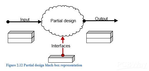
If the partial design has inputs, the inputs will be represented by using an input arrow as shown in the figure above. Outputs are represented in a similar way. We also have an arrow that represents the interface and the name of the interface can be mentioned as well.
Once the system has been divided into partial designs, one or more solutions should be found for each single partial design. Do not go into detail this time but just try to find some sort of direction in which we can find the solution. An example can be found while thinking about how to transform an analog signal into a digital one. This can be realized by using a DAC or a R/2R network or even an ASIC. (To name a few).
Mechanical parts can also be included in this part of the design process. An example of this is a door opener. A few possible solutions are drawn below.

In the next stage you will work out every detail for one possible solution per partial design. It is not always necessary to think of more than one solution for partial designs. Sometimes, there is instant clarity when you think of a solution. However, it is recommended to consider other options that might cost less or are more reliable.
Finding solutions
There are several options to find solutions to your challenge. (By Challenge, I mean the fact that you have to find possible solutions for your design). First of all, a designer should use his personal experience and the experience of the team, colleagues and working environment. They can be a great source of inspiration.
What did we do before and how can we use that now?
Moreover, it can be rewording to look around. How did others do this? What is available on the market? Whenever you start working on a project by yourself or as part of a team let me remind you that there are already many tools available that have proven their worth to many alike. Many tools will be addressed later but let me give you some ideas.
First, there is the well known brainstorm session in which a group of people shares ideas. Another method that is less known to many is the brain writing. Both techniques have the same purpose to stimulate the creativity of the designers. Depending on the number of people involved in a brainstorm session, it can be rather expensive because many people are involved simultaneously and the duration of a session is time consuming.
Brain writing on the other hand is a lot less expensive. A simple brain writing session takes only a few minutes per participant. More of these interesting methods will be described later.
When all partial designs are defined, the designer has to make a choice. This is the time that the designer chooses what possible solutions will be designed in detail during the CREATE stage.
At this point, it is essential to know all prospects of a possible solution. Every designer has a backpack of experience but the content of this backpack is different for everyone. Nevertheless, experience troubles the mind. Someone who has more experience with a certain technology might be prejudiced. A designer’s experience and expertise will have a big influence on the choices he will make. This is not necessary a bad thing! Also, it could be useful to pick someone else’s brain on these matters. Two heads are better than one.
The toolbox, as described later on in the book, will hand you some tools that can be used during the DESIGN stage.
Morphologic Table
If a choice has to be made about what possible solutions to use for a partial design, the use of a morphologic table will prove to be very useful. A Morphologic table shows the designer all the possible solutions for all partial designs in one table. Once a choice has been made, the chosen solutions are connected using a line. That way it is not only possible to see all the solutions, but also the solutions that will be used in the CREATE stage.

Step 3: The Create Stage
The DESIGN Stage has been completed and a the morphologic table.
The context diagram shows a static link between the product and the environment. In order to get to know the dynamic properties it would be better to make use of Use Case diagrams and use cases.
Use Case s work best if used for the whole system, software and hardware.
The CREATE stage should include all information necessary to complete a design. This could therefore include information about the PCB design or the part list or others. It is up to the designer to decide what to include. Usually, an assembly drawing of the printed circuit board will suffice. Documentation for producing the product is usually kept separately.
Step 4: The Validate stage
The VALIDATE stage should not be looked at as an isolated stage but more as a lifeline throughout the whole process of designing. It is very important to keep the specifications and requirement of the product in mind at all times. Only then, a designer can tune and adjust the design on time, if necessary.
However, there will be a time to test your design and to check if the design complies with what has been agreed upon.
This is done during the VALIDATE Stage. To validate all, the designer can use the same table that was created during the SPECIFY stage. Now the purpose of the last column will be clear. Only if all the specifications and requirements are checked, the product is ready to be handed over to the customer.

It is important to document any specification that is not compliant. No matter what stage in the design process you are in! That is the only way to prevent having the same discussion over and over again and it helps others to understand the decisions that have been made.
Of course, it is easy to look at a table that the designer most likely made by himself and to mark every item in the last column. The question is how others can check that everything is compliant to the specifications. This is exactly why writing testing procedures is necessary. Not all can be tested by following procedures but they should be used whenever possible. Procedures for testing and validating products create trust in the product. Also, if correctly documented, anyone could test a product for you.
The VALIDATE stage is perfect for tightening up your specifications. During the SPECIFY stage some specifications might be open for discussion but during this stage, discussion is no longer an option. Everything has to be clear. Specifications like “a minimum of 4 inputs” can now be better describes: “4 inputs”. Or maybe you added some extra: “8 inputs”.
If all specification and requirements are met, the product will not be changed any further during this design process. If the customer wants to change something he should place another order for a new project, right?
If the budget allows, you could ask a colleague to look at the product and you could let him try to write down the specifications that are discovered while testing the product. Do not give him the list of specifications you already have. He might look at the product differently and you might find some new interesting specifications.


