Summary: In this post, I build some IEC64W IEEE-488 parallel interface adapters for the Commodore 64/128, using PCBs from PCBWay!
I recently repaired and restored a 1983 Commodore 2031-LP 5.25″ floppy drive, which is unusual in that it uses the came IEEE-488 parallel interface as the earlier Commodore PET series of computers (GPIB connector), as opposed to the IEC serial interface used by the later Commodore 8-bit series of computers (DIN connector).
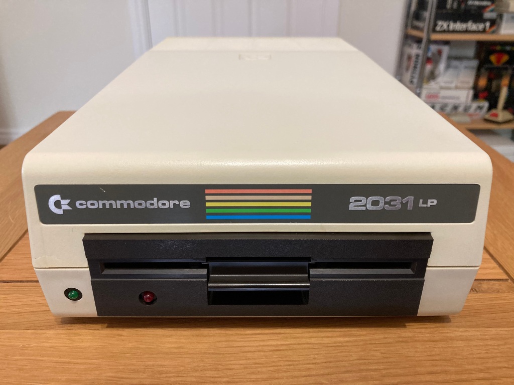 Commodore 2031-LP 5.25″ FDD.
This made testing the 2031-LP floppy drive throughout the repair difficult, as although I do own a Commodore PET (a PET 3032 to be exact), these computers are not exactly easy to move around and they take up a lot of physical space, which is not ideal as I do most of my tinkering in my shed workshop and I only have a limited amount of space available. I therefore spent some time investigating potential alternatives.
The most practical option seemed to be an IEEE-488 parallel adapter for the Commodore 64 & 128, such as the IEC64W – this was an original card that was distributed by several German companies (JANN Datentechnik from Berlin, REX Datentechnik from Hagen, and WAW Elektronik from Berlin), which has since been reverse-engineered in an excellent and very commendable effort by Dirk Wouters of RetroTinkerer.net.
 IEC64W IEEE-488 parallel adapter (image credit: IEC64W on GitHub).
The IEC64W uses a 6821 Peripheral Interface Adapter (PIA) to drive the IEEE-488 parallel bus directly, as opposed to using standard 75160 and 75161 driver ICs. Aside from that, is has a couple of 74-series logic ICs, some passives (including a DIP switch block for configuration), and a ROM (either a 2764 or 27128 EPROM).

IEEE-488 parallel interface pinout (image credit: AutomationForum).
Building a set of IEC64W adapters
At the time of the 2031-LP repair, only a very limited number of sellers (such as some eBay sellers) sold IEC64W adaptors, none of which were in the UK, so I had to make my own.
This wouldn’t be too much of a problem, as Dirk had very kindly hosted the necessary design and firmware files as open hardware on their GitHub page, and also (very helpfully) as a shared project on the PCBWay Shared Projects page.
I decided to order a set of these PCBs (10 total) through PCBWay because of how easy it is to order their shared project PCBs, and I had a very good experience overall.
Aside from the PCBs, several other components are required – per board, this includes:
 IEC64W parts.
I built up an IEC64W board to test out, which is relatively simple process but takes quite some time (and is very repetitive!) due to the large number of solder joints.


IEC64W board built up.
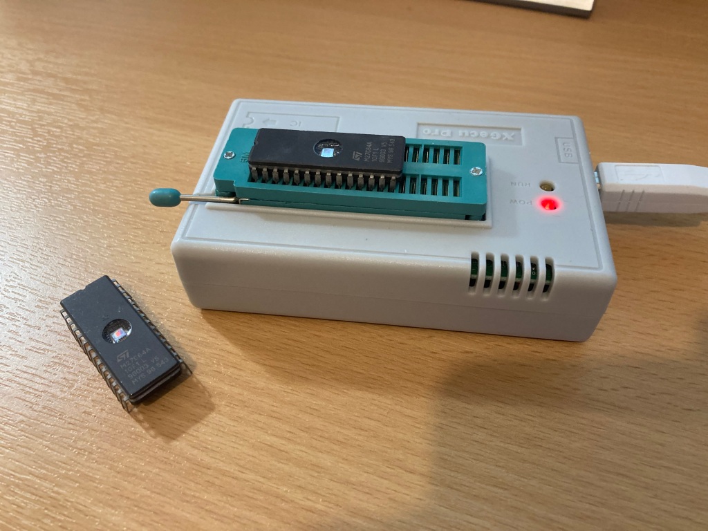
For the onboard Kernal ROM, I bought some 27128 EPROMs on AliExpress – these appeared to be rebranded parts (i.e. branded ST but actually AMD parts according to the chip ID), but they seem to be genuine 2764 EPROMs and they work fine.
First of all, I erased some of the 27128 EPROMs using a UV EPROM eraser. Unlike EEPROMs which are electrically-erasable, EPROMs (which have cute little windows on top of them) need to be erased prior to programming using UV light.
 EPROMs and UV eraser.
Then, I programmed up one of the pre-erased 27128 EPROMs using one of the firmware files that Dirk Wouter had very kindly provided, which I have also hosted online.
I decided to use the “JANN Kernal C128-C64” binary file, which will work with earlier Commodore 64 long-boards (which use a 2364 Kernal ROM) and the Commodore 128 (in C64 mode) – there is also a version for the later Commodore 64 short-boards, which use a 27128 combined Kernal & BASIC ROM).
 EPROMs during programming.

27128 EPROM programmed correctly.
I then read back and verified the ROM contents using HexCmp2.
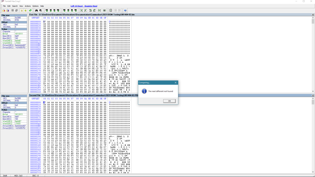 Programmed EPROM reads and verifies correctly.
I then printed and attached a label to cover the erase window.


ICE64W adapter completed.
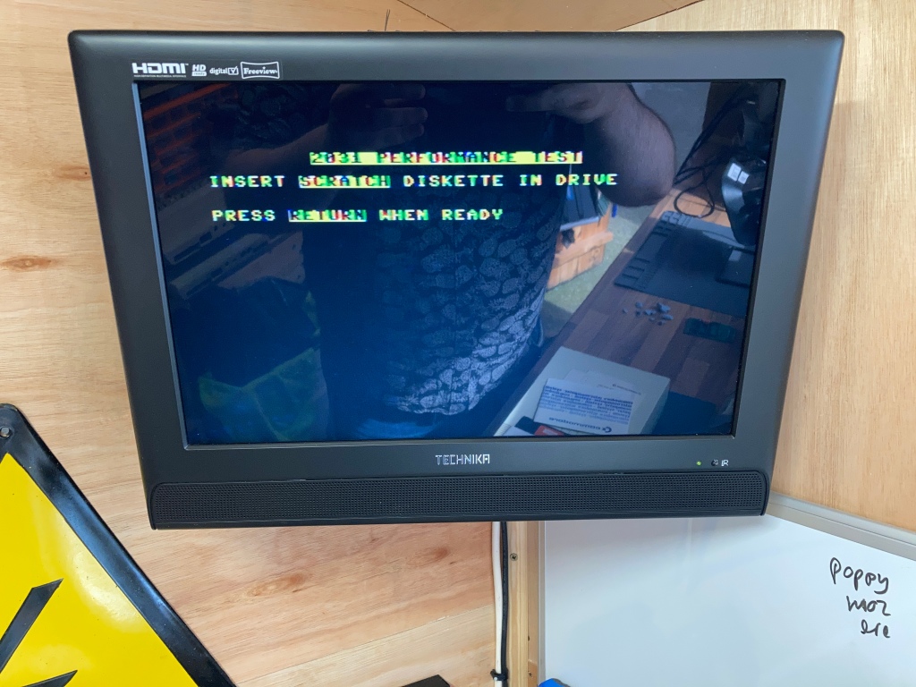
After fitting the EPROM and the other ICs into the sockets on the first IEC64W board, I gave it a test with the 2031-LP and my Commodore 128 test board, and it seemed to work OK.


IEC64W adapter working on a Commodore 128.
I also tested it on my Commodore 64 “breadbin” with an earlier long mainboard.

IEC64W adapter working on a Commodore 64 “breadbin”.
How to use the IEC64W
Setting the DIP switches
DIP switch settings: AABXCC (123456)
Review of PCBWay
I’m quite new to ordering custom PCBs (as a hobbyist, at least), so I thought I’d write a quick review of PCBWay to help out other new starters. These are the third set of PCBs that I’ve ordered from PCBWay and I’ll definitely be buying more in the near future – I’d eventually even like to work my way up to developing my own circuit designs and layouts.
The minimum order quantity for these small PCBs was 5, at $5.00 per set, and 10 PCBs were also $5.00 (bargain!).
When you add a design (or designs) to your online shopping cart, they will go through a short review process by your assigned sales rep. In my case, this took less than an hour.
Once you’ve placed your order, you are taken to a detailed order manufacturing screen, where you can track the process through each exact manufacturing step. I chose a 24-hour build time for this project, which was standard at no extra cost, and my boards were shipped the next working day.
Shipping via DHL (2-4 working days) between China and the UK cost around £20.00 for this order, and the parts arrived safely and extremely quickly. There are cheaper shipping options available (i.e. China Post), but these will take significantly longer to arrive, and there are medium-cost options (including PCBWay’s own shipping service) which are a compromise between delivery time and cost.
For this order, I wasn’t subject to any import charges, but this may apply to orders of greater value – these are the responsibility of the buyer, and will be paid following delivery.
My order was well packed, and the PCBs are of a very good quality, and work exactly as intended! PCBWay’s communication and service throughout the process was also very good, and I’m very pleased with my experience overall.
The PCBWay Shared Projects page is extremely useful for quick prototyping, or for those like myself who don’t currently have any of their own designs. Its integration with the ordering process is seamless, so it’s very easy for hobbyists to get boards made. Shared project authors also get paid for their work when you buy, which is fantastic.
There are lots of shared projects available for vintage computing enthusiasts in particular, and PCBWay seems to have a good standing in the community. If anyone has a project that they would like to share on the PCBWay page, they can do so here.
I hope this helps any PCB newbies like myself! If you have any questions, let me know and I’ll try to help out if I can.
You can claim your $5.00 PCBWay new user voucher here, if you so wish.
Original post on my website: https://retrorepairsandrefurbs.com/2022/06/27/iec64w-ieee-488-parallel-interface-adapters-for-the-commodore-64-128/


