


Build your own long-range weather station with Lora GPS anemometer module
In this tutorial we will see how to create a weather station, for places where there is no internet access with LORA modules, GPS, Temperature and humidity sensor DHT11, but I recommend the DHT22, we will also work with an anemometer to measure the wind speed, as a controller of the system we will use an arduino nano.
Electronic Components
MODULES LORA DRF1276DM/DRF1278DM
introduction
The LoRa radio module is a type of long-range low-data rate data radio modem based on Semtech’s Sx1276. It is a low-cost transceiver module of less than 1 GHz designed for operations in the ISM (Industrial Scientific Medical) and LPRD bands without a license. Frequency spectrum modulation/demodulation, multichannel operation, high bandwidth efficiency and anti-lock performance make LoRa modules easy to perform thanks to the robust and reliable wireless link.
The module can operate in two different modes: standard mode and Star network mode. In standard mode, it acts as a transparent data radio modem that communicates with the host in the preset data format without the need for encoding/decoding. In home network mode, one module will be configured for the central node and other modules will be configured as node modules. Communication between the central module and the node module is bidirectional, but the node modules cannot communicate with each other. Note that the module does not contain the lorawan protocol. Therefore, the star networking function of this module is used with the protocol itself, so it does not support lorawan.
characteristics
LoRa frequency spectrum
Frequency band 433 / 490Mhz ISM
-137 dBm receive sensitivity
20 dBm max. output power
Activation serial port
Wireless alarm clock
Star network capacity
Supply voltage 3.4~5.5V
specification
Operating voltage: 2.1~3.6V (battery powered) or 4.5~5.5V
Working frequency band: 433 MHz
Modulation: Extended Spectrum LoRa
Output power: ≤ 20dBm
Reception sensitivity: -148dBm
Emission current: ≤120mA
Receiving current: ≤15.2mA
Sleep current: ≤ 3.9uA
Sleep time: optional 2S, 4S, 6S, 8S, 10S
Breathing time: optional 2ms, 4ms, 8ms, 16ms, 32ms, 64ms
Waking up time: waking up immediately
Communication interface: TTL serial communication
Serial transmission speed: 1200~57600.9600bps (default)
Serial port verification: 8E1,8O1,8N1 (optional)
Operating temperature: -40°C – +80°C
Product size: 34.2 * 18.4mm / 1.35 * 0.72in


Data Sheets
DRF1276DM
DRF1278DM
PIN OUT

Connecting Module with Serial USB Adapter

SETTINGS
For some applications, default parameters may not be the best
choice, so users may need to change the parameters There are two ways to adjust them: per MCU or per PC. In
configuration mode, the EN pin must be connected to
GND and then the configuration tool or commands can work effectively
By PC: DORJI offers a PC-based configuration tool
that can be used to change parameters through the graphical interface. Users can insert the DRF1278DM module into
serial usb adapter and connect them to the computer and run the configuration tool.
DRF TOOL
This tool allows us to configure the LoRa modules DRF1278DM and DRF1276DM
Download—drftool >

Description of the program
UART -> Values are set to 9.6k bps and no parity check
RF frequency–> Indicates the center frequency of the RF carrier
RF Mode–> Standard Mode, Center Mode, and Node Mode
RF_Factor–> Lora scattering factor. A higher value means
higher sensitivity but longer air transmission time. Only users can change it in standard mode
RF_BW–> Lora bandwidth. A higher value means lower sensitivity. Recommended value: 125K. Only users can change it in standard mode.
Node ID–> Only used for modules in node mode: 0~65535
Net ID–> Only modules with the same network ID (0~255) can communicate
with each other. Can avoid module interference
Power–> Used to configure the output power of the DRF1278D. There are 7 power levels. 7 means the maximum. an output power: 20dBm and 0 means the lowest output power
Breath–> The activation period for the module in node mode. Only available for firmware 2.0 or higher
Wake timer–> The time to detect the wireless signal during the
break period is only available for firmware 2.7 or higher
Serial Transmission Rate–> Defines the data rate between DRF1278DM and the host (pc or microcontroller)
Serial parity–> Defines parity checking between DRF1278DM and the host (pc or microcontroller)
STANDARD
MODE Standard mode is also called transparent mode in
which the module receives or sends data to the host through the serial port (UART) in the preset data format and users do not need to worry about processing data within the module. The DRF1278DM AUX
pin will give indication about the serial port IN/OUT data 2 ms in advance, which can be used to wake up the host. In this mode, the EN pin must be set
to low logic in case the module enters deep sleep.
In STANDARD or transparent mode, the nodes can operate with a point-to-point (P2P) connection the main feature of this mode is that an intermediary device is not required to manage the communication, the devices can send information to each other directly, this is perfect for simple communications such as the ignition of a light.
The other way is with a star network type where we find a central node that is responsible for managing the network, its disadvantage is that it is limited to 255 networks of 255 nodes* and that the coordinating node can only listen to one node at a time.
STAR
NETWORK MODE In this mode, a DRF1278DM module needs
to set a module as the central module and other modules must be node modules for star networks. For the core module, it works at
full performance so its power consumption is
the same as in standard mode and the EN pin must be connected to low logic. The logical level of the
SET pin for the central module must be the same as the node module.
GT-U7 GPS Module
Initial test settings
For a quick test using your Windows computer, you just need to establish serial communication with the GPS module using a USB-UART adapter like the PL2303 USB-to-Serial module or similar. The hardware configuration is quite simple:
GT-U7 GPS ModuleUSB to Serial ConverterTxRxRxTxGndGndVdc5 V

Note that when the GPS module works, the green indicator on the GPS module will flash (red is for indication of ignition), and the relative figures, time(UTC), latitude, longitude, and more. If we establish a connection between the GPS module, and a serial terminal program on our pc we will obtain data. It is important to try to be in a clear area to capture satellite signals, at least we need 3 salelites, to get latitude and longitude data, but the more satellites we get the better the navigation experience and accuracy.
Product description
Item Description:
Features: GT-U7 module. Module of high sensitivity, low static deviation, low power consumption and low volume.
Miniaturization: thanks to the extremely high tracking sensitivity, the position of the cover has been considerably improved.
– High precision: In a narrow urban sky, in harsh jungle environments, the GT-U7 can be positioned with great precision.
Easy to use: with the IPEX antenna interface the standard distribution of the active antenna can be placed quickly. Table of rechargeable button batteries. Onboard E2PROM allows the storage of parameter data.
-Compatible: The output format is compatible with NEO-6M.
– Scope: vehicles, mobile devices such as PDA, vehicle surveillance, mobile phones, camcorders and other mobile location systems, bicycle sharing, common mobile power supply.
Contenido del paquete:
1 módulo GPS GT-U7 .
1 antena activa con interfaz IPEX.
Especificación:
Con la interfaz de antena IPEX, la distribución predeterminada de la antena activa, se puede colocar rápidamente
Voltaje de funcionamiento: 3.6V-5V (o fuente de alimentación USB directa)
Velocidad de transmisión en baudios: 9600 (se puede modificar)
Batería de botón recargable a bordo
Memoria E2PROM a bordo
Formato de salida NEMA de datos de parámetros es compatible con NEO-6M
Tama?o: 27.6 mm * 26.6 mm se puede insertar o seleccionar un parche (con orificios de posicionamiento)
áreas de aplicación: Dispositivos portátiles montados en vehículos como PDA
Monitoreo de vehículos
Teléfonos móviles, videocámaras y otros sistemas de posicionamientos móviles
PinOut
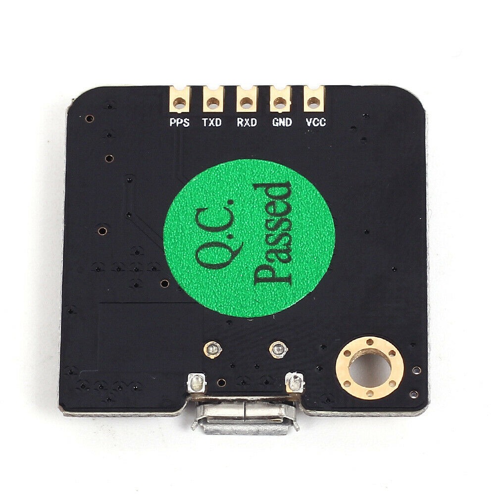
PPS: Pulso por segundo
TXD: Pin de transmisión de datos
RXD: Pin de transmisión de datos
GND: Tierra
VCC: Voltage de alimentación 3.6 a 5.5 voltios
Visión general
La serie de módulos GT-U7 es una familia de receptores GPS autónomos con alto rendimiento con motor de posicionamiento u-blox 6. Estos receptores flexibles y rentables ofrecen numerosos opciones de conectividad en un paquete en miniatura de 16 x 12,2 x 2,4 mm. Su arquitectura compacta y las opciones de alimentación y memoria hacen que los módulos GT-U7 sean ideales para dispositivos móviles que funcionan con baterías con
limitaciones de espacio y costos muy estrictos. El motor de posicionamiento u-blox 6 de 50 canales cuenta con
Time-To-First-Fix (TTFF) de menos de 1 segundo. El motor de adquisición dedicado, con 2 millones correladores, es capaz de realizar búsquedas masivas de espacio de tiempo / frecuencia en paralelo, lo que le permite encontrar
satélites al instante. El dise?o y la tecnología innovadores suprimen las fuentes de interferencia y mitigan efectos multi trayecto, dando a los receptores GPS GT-U7 un excelente rendimiento de navegación incluso en la mayoría
entornos desafiantes.
GPS asistido (A-GPS)
Suministro de información de ayuda como efemérides, almanaque, última posición aproximada y hora y satélite
el estado y una se?al de sincronización de tiempo opcional reducirán significativamente el tiempo para arreglar por primera vez y mejorar la sensibilidad de adquisición. Todos los módulos GT-U7 son compatibles con u-blox AssistNow Online y los servicios AssistNow Offline A-GPS11 y son compatibles con OMA SUPL.
AssistNow Autónomo
AssistNow Autonomous proporciona una funcionalidad similar al GPS asistido sin la necesidad de un host o conexión de red externa. Basado en datos de efemérides satelitales transmitidos previamente descargado y almacenado por el receptor GPS, AssistNow Autonomous genera automáticamente datos orbitales satelitales precisos (“datos autónomos de AssistNow”) que se pueden utilizar para futuros posiciones GPS. Los datos de AssistNow Autonomous son fiables hasta 3 días después de la captura inicial.
Protocolos e interfaces
Tipo de protocolo
Entrada / salida NMEA, ASCII, 0183, 2.3 (compatible con 3.0) Entrada / salida UBX, binaria, u-blox entrada RTCM patentada, 2.3
UART
Los módulos GT-U7 incluyen una interfaz UART configurable para comunicación en serie.
USB
Los módulos GT-U7 proporcionan una interfaz USB versión 2.0 FS (velocidad completa, 12 Mbit / s) como alternativa a la UART. La resistencia pull-up en USB_DP está integrada para se?alar un dispositivo de velocidad completa al host. El pin VDDUSB suministra la interfaz USB. u-blox proporciona un controlador USB certificado por Microsoft? para Sistemas operativos Windows XP, Windows Vista y Windows 7.
Serial Peripheral Interface (SPI)
The SPI interface allows the connection of external devices with a serial interface, p. E.g. serial flash to save AssistNow Offline A-GPS settings and data or to connect to a host CPU. The interface can be operated in master or slave mode. In master mode, a chip selection signal is available to select external slaves. In slave mode, a single chip selection signal allows communication with the host.
Power management
U-blox receivers support different power modes. These modes represent strategies of how to control the acquisition and tracking engines in order to achieve the best possible performance or good performance with reduced power consumption.
Maximum
performance mode During a cold start, a receiver in peak performance mode continuously deploys the acquisition engine to search for all satellites. Once the receiver has a fixed position (or if pre-positioning information is available), the acquisition engine continues to be used to search for all visible satellites that are not being tracked.
Eco-mode
During a cold start, a receiver in Eco mode works exactly as in maximum performance mode. Once a position can be calculated and a sufficient number of satellites are being tracked, the acquisition engine shuts down, resulting in significant energy savings. The tracking engine continuously tracks the acquired satellites and acquires other available or emerging satellites.
Power saving mode
Power saving mode (PSM) allows a reduction in the system’s power consumption by turning parts of the receiver on and off.
This product is accompanied by a gps module, feet for welding, a ceramic antenna.


Arduino nano

The Arduino Nano is a small board, complete and compatible with the test board based on the ATmega328 (Arduino Nano 3.x). It has more or less the same functionality as the Arduino Duemilanove, but in a different package. It only lacks a DC power connector and works with a Mini-B USB cable instead of a standard one.
microcontrollerATmega328architectureAVROperating voltage5 VFlash memory32 KB of which 2 KB uses the boot loaderSram2 KBClock speed16 MHzAnalog PINS IN8Eeprom1 KBDC current by I/O pins40 mA (I/O pins)Input voltage7-12 VDigital I/O pins22 (6 of which are PWM)PWM output6Energy consumption19 mAPCB size18 x 45 mmweight7 g
Pin diagram

A DHT11 Temperature and Humidity Sensor

This module consists of a digital humidity and temperature sensor DHT11 and a resistance of 1 kΩ. The DHT11 uses an internal thermistor and a capacitive humidity sensor to determine environmental conditions, an internal chip is responsible for converting the readings to a serial digital signal.
Operating voltage3.3V to 5.5VHumidity measurement range20% to 90% HRMoisture measurement accuracy± 5% HRHumidity measurement resolution1% HRTemperature measurement range0oC to 50oC [32oF to 122oF]Temperature measurement accuracy± 2oCTemperature measurement resolution1oCSignal transmission range20m
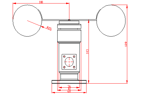
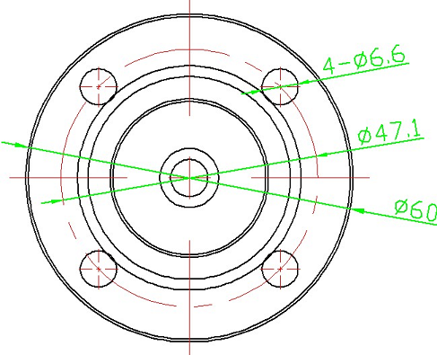
Anemometer JL-FS2
introduction
Have you ever wanted to build your own weather station? This anemometer is made of housing, wind cups and circuit module. It has built-in photovoltaic module, industrial microcomputer processor and standard current generator. Made of aluminum alloy, the anemometer is of high strength, weather resistance and corrosion resistance. The military-grade interface ensures a long service life of this anemometer, while improving the accuracy of wind speed acquisition.
Along with other components, this anemometer can be widely used to measure wind in areas such as engineering, railways, docks, power plants, meteorological, cable car, environmental study, agriculture, energy monitoring, health study with corresponding signal output.
With the instructions and sample code, users can easily get the wind speed level through the voltage signal output (0 to 5v).
The three-type wind speed sensor is an instrument that can measure wind speed. It is composed of the housing, the wind cup and the circuit module. Photovoltaic modules, industrial microcomputer processor, current generator, electric current, etc. are integrated into the inside handle.
The materials of the sensor housing and wind cup are aluminum alloy that uses special mold precision casting technology, the tolerance size is very small, the surface accuracy is very high and the internal circuit has been processed for protection, the sensor has high resistance , weather resistance, corrosion resistance and waterproof.
The cable plug is a military plug, has a good anticorrosive performance and prevents erosion that can guarantee the instrument used for a long time, at the same time, in the case of using relevant specifications that guarantee the accuracy of the wind. speed acquisition.
The printed circuit board material is military grade A which guarantees the stability of the parameters and the quality of the electrical properties; the electronic components are all imported industrial chips, which makes it generally have extremely reliable electromagnetic interference resistance and can ensure that the host can work normally at -20°C~+50°C, humidity at 35%~85% (condensation).
This product can be widely used in engineering machinery (crane, crawler crane, door crane, tower crane, etc.), railways, ports, docks, power plants, meteorology, cable car, environment, greenhouse, breeding, air conditioning, energy monitoring. , agriculture, health, clean room areas such as wind speed measurement and corresponding signal output.
DFROBOT offers you the anemometer sensors, your wind speed was judged by adopting the output voltage signal (0 to 5 v), users can easily read the wind speed level with our instructions and sample code.
specification
Style: three cups
Material: aluminum alloy.
The mode of your output signal: 0-5 V (voltage signal)
supply voltage: DC 9-24V
Power consumption: MAX voltage≤0.3W
Start wind speed: 0.4-0.8 m / s
Resolution: 0.1 m/s
Effective wind speed measurement range: 0-30 m/s
System Error: ± 3%
Transmission distance: more than 1000 m
Transmission medium: cable transmission
Connection mode: three-wire system
Working temperature: -40°C~80°C
Working humidity: 35%~85
feature
High hardness
Corrosion protection
impermeability
High accuracy
Please make the external power (DC 9-24V) and wiring to Arudino on the same ground, i.e. connect GND to arduino as well as to the GND of the external power In the diagram, it is not indicated.

Red —— + 9-24V
Black —- GND
Yellow — voltage signal
Blue —– current signal
Dimensions of the anemometer
Relationship between velocity and output value
Formula: V=6*U (multiply by 6 to get the speed value in meters per second)
Wind SpeedValue10.1720.3330.540.6750.836171.1781.3391.5101.67111.83122132.17142.33152.5162.67172.83183193.17203.33213.6223.67233.83244254.17264.33274.5284.67294.83305
Female pins

A socket for the arduino nano

Male pins
Two resistors of 1 Kohm

Pcb

Download the Gerber –> lora remote weather PCB_Estacion file
#include <SoftwareSerial.h>//Librería para emular un puerto serial por software #include <TinyGPS.h>//Librería para obtener datos del GPS #include "DHT.h" TinyGPS gps; SoftwareSerial ss(4, 3);//Pines donde conectaremos el módulo GPS // Descomenta la linea dependiendo del sensor que vallas a usar #define DHTTYPE DHT11 // DHT 11 //#define DHTTYPE DHT21 // DHT 21 //#define DHTTYPE DHT22 // DHT 22 #define DHTPin 5 //Pin del sensor DHT; DHT dht(DHTPin, DHTTYPE); float t; float h; String datos; String stringT; String stringH; int velocidad; float voltaje; unsigned long Tiempo = 0; void setup() { dht.begin();//Inicializar el sensor DHT Serial.begin(9600);//Velocidad del puerto serial del Arduino debe conincidir con la del módulo Lora ss.begin(9600);//Velocidad del módulo GPS Serial.println("Iniciando envío de coordenadas con TinyGPS v. "); Serial.println(TinyGPS::library_version()); } void loop() { bool nuevosDatos = false; unsigned long caracteres; unsigned short sentencias, fallas; // Analizamos si hay datos del módulo GPS cada 10 segundos for (unsigned long start = millis(); millis() - start < 10000;) { if(millis() > Tiempo + 10000){ Tiempo = millis(); sensores(); } while (ss.available())//Se cumple mientras hay datos disponibles desde el GPS { char c = ss.read(); if (gps.encode(c)) // Si hay datos validos nuevosDatos = true;//Asignamos un valor "true" a la variable } } if (nuevosDatos) { float flat, flon;//Variables para almacenar la latitud y longitud gps.f_get_position(&flat, &flon); Serial.print(" https://maps.google.com/maps?q=");//Formato url de google maps Serial.print(flat == TinyGPS::GPS_INVALID_F_ANGLE ? 0.0 : flat, 2);//Obtenemos la latitud Serial.print(","); Serial.println(flon == TinyGPS::GPS_INVALID_F_ANGLE ? 0.0 : flon, 2);//Obtenemos la longitud } //En el caso de que exista una mala conexión con el GPS, en el cableado, nos enviará una alerta gps.stats(&caracteres, &sentencias, &fallas); if (caracteres == 0) Serial.println("*No se han recibido caracteres del GPS: compruebe el cableado*"); } void sensores(){ h = dht.readHumidity();//Lectura de la humedad t = dht.readTemperature();//Lectura de la temperatura //Lo convertimos a string stringT = String(t); stringH = String(h); int valorAnemometro = analogRead(A0);//Leemos el pin analógico A0 voltaje = valorAnemometro * (5.0 / 1023.0);//Convertimos ese valor en voltaje velocidad = 6*voltaje;//El nivel de velocidad del viento es proporcional al voltaje de salida. datos = "Temp:"+ stringT + "C Hum:" +stringH + "% V.Viento:" +velocidad + " M/S "; Serial.println(datos);//Enviamos estos datos al módulo Lora }
More information https://rogerbit.com/wprb/2021/07/build-your-own-long-range-weather-station-with-lora-gps-anemometer-module/
Build your own long-range weather station with Lora GPS anemometer module
*PCBWay community is a sharing platform. We are not responsible for any design issues and parameter issues (board thickness, surface finish, etc.) you choose.


Raspberry Pi 5 7 Inch Touch Screen IPS 1024x600 HD LCD HDMI-compatible Display for RPI 4B 3B+ OPI 5 AIDA64 PC Secondary Screen(Without Speaker)
BUY NOW


- Comments(0)
- Likes(4)
More by CarlosVolt Tutoriales
-
 Infrared stepper motor control with speed control
More info and updates https://rogerbit.com/wprb/2024/09/motor-paso-a-paso-x-infrarrojo/In this proje...
Infrared stepper motor control with speed control
More info and updates https://rogerbit.com/wprb/2024/09/motor-paso-a-paso-x-infrarrojo/In this proje...
-
 Uploading BME280 Sensor Data to ThingSpeak Using ESP32
In this tutorial, we will show you how to connect a BME280 sensor to an ESP32 to read temperature, h...
Uploading BME280 Sensor Data to ThingSpeak Using ESP32
In this tutorial, we will show you how to connect a BME280 sensor to an ESP32 to read temperature, h...
-
 Water pump control for irrigation via telegram and esp32
Water Pump Control by Telegram and ESP32 is an automated system that allows you to remotely control ...
Water pump control for irrigation via telegram and esp32
Water Pump Control by Telegram and ESP32 is an automated system that allows you to remotely control ...
-
 Air conditioning on/off control via telegram and esp32
In this tutorial we will see how to control an air conditioner, with an esp32 and the telegram appli...
Air conditioning on/off control via telegram and esp32
In this tutorial we will see how to control an air conditioner, with an esp32 and the telegram appli...
-
 35 watt stereo amplifier
In this video we will see how to build an audio amplifier, with the TDA7377 integrated circuit, and ...
35 watt stereo amplifier
In this video we will see how to build an audio amplifier, with the TDA7377 integrated circuit, and ...
-
 Laser alarm with RFID module
More info and updates in https://rogerbit.com/wprb/2024/08/alarma-laser-rfid/In this project, we bui...
Laser alarm with RFID module
More info and updates in https://rogerbit.com/wprb/2024/08/alarma-laser-rfid/In this project, we bui...
-
 Control lights by voice commands and keys
In this tutorial we will see how to create a device to control lights by voice commands, with a modu...
Control lights by voice commands and keys
In this tutorial we will see how to create a device to control lights by voice commands, with a modu...
-
 Stepper motor control x bluetooth and app
In this tutorial we will see a circuit, which controls a stepper motor, with an application made in ...
Stepper motor control x bluetooth and app
In this tutorial we will see a circuit, which controls a stepper motor, with an application made in ...
-
 DFplayermini x bluetooth mp3 player control
More info and updates in https://rogerbit.com/wprb/2022/12/dfplayermini-x-bluetooth/In this tutorial...
DFplayermini x bluetooth mp3 player control
More info and updates in https://rogerbit.com/wprb/2022/12/dfplayermini-x-bluetooth/In this tutorial...
-
 Robot with WiFi control and servos driven by ESP32
More info and updates in https://rogerbit.com/wprb/2023/07/robot-wifi/A robot controlled by Wi-Fi, s...
Robot with WiFi control and servos driven by ESP32
More info and updates in https://rogerbit.com/wprb/2023/07/robot-wifi/A robot controlled by Wi-Fi, s...
-
 How to make a water level meter with uln2803
In this tutorial we will see how to make a water level meter circuit with the built-in uln2803.The p...
How to make a water level meter with uln2803
In this tutorial we will see how to make a water level meter circuit with the built-in uln2803.The p...
-
 Color Detector with Arduino and OLED display
In this tutorial we will show you how to build a color detector using the TCS3200 sensor and an SH11...
Color Detector with Arduino and OLED display
In this tutorial we will show you how to build a color detector using the TCS3200 sensor and an SH11...
-
 DTMF decoder for handy with arduino, control over several kilometers
In this tutorial we will see how to make a circuit to connect to our handy, in this case a Baofeng U...
DTMF decoder for handy with arduino, control over several kilometers
In this tutorial we will see how to make a circuit to connect to our handy, in this case a Baofeng U...
-
 Turn on light from thindspeak with esp32
In this tutorial, we will show you how to control lights over the Internet using an ESP32 and the Th...
Turn on light from thindspeak with esp32
In this tutorial, we will show you how to control lights over the Internet using an ESP32 and the Th...
-
 MP3 player control with webserver using ESP32 WIFI
In this tutorial, you will learn how to build a web server using the ESP32 to control the YX5300 mod...
MP3 player control with webserver using ESP32 WIFI
In this tutorial, you will learn how to build a web server using the ESP32 to control the YX5300 mod...
-
 Time clock with fingerprint IoT module, uploading data to thingspeak
More info in and updates in https://rogerbit.com/wprb/2022/07/reloj-de-control-fingerprint/In this t...
Time clock with fingerprint IoT module, uploading data to thingspeak
More info in and updates in https://rogerbit.com/wprb/2022/07/reloj-de-control-fingerprint/In this t...
-
 Make your own logic tip (includes printed circuit board)
In this video tutorial we will see how to make a logic tip, on a printed circuit, with the integrate...
Make your own logic tip (includes printed circuit board)
In this video tutorial we will see how to make a logic tip, on a printed circuit, with the integrate...
-
 Coil or inductor meter with Arduino and OLED display
More info and updates in https://rogerbit.com/wprb/2022/06/medidor-inductores/In this tutorial we wi...
Coil or inductor meter with Arduino and OLED display
More info and updates in https://rogerbit.com/wprb/2022/06/medidor-inductores/In this tutorial we wi...
-
-
ARPS-2 – Arduino-Compatible Robot Project Shield for Arduino UNO
1879 0 5 -
A Compact Charging Breakout Board For Waveshare ESP32-C3
2485 3 7 -
AI-driven LoRa & LLM-enabled Kiosk & Food Delivery System
2563 2 0 -
-
-
-
ESP32-C3 BLE Keyboard - Battery Powered with USB-C Charging
2666 0 2 -


