


|
arduino IDEArduino
|
ATTiny1616 Minimal Breakout board - QFN
Breaking out of the Chip Shortage – Attempt #2
The ATTiny1616 is a step up from the ATTiny202, having more GPIO, flash and RAM. This makes it ideal for bigger, but still medium size projects that do not need all the power of the traditional Arduino.
In Part 1 of this series, I took a quick look at the ATTiny202 MCU from Microchip. Having only 5 usable GPIO, with limited Flash and Ram, that little chip was still quite useful for some of those very small projects, where we did not really need a lot of peripherals and GPIO pins.
Today, we shall take a step up, and take look at a slightly bigger MCU, the ATTiny1616, this time with up to 17 GPIO pins, more flash and memory, and still quite easy and cheap to get hold of. (Current Prices are in the range of about $ 1 USD to $ 2 USD, depending on where you buy and how many you buy).
As I wanted to give myself a bit of a challenge with this project, I decided on using a QFN package this time, which, being extremely tiny, only 3mm x 3mm, will give most Makers a pleasant challenge to solder correctly. ( I am planning a SOIC 20 version but with a bit more external hardware onboard)
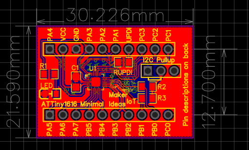
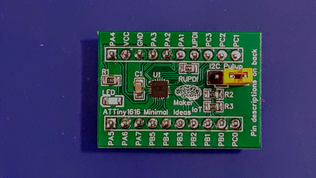 MakerIoT2020 ATTiny1616 Minimal Breadboard-friendly breakout
The ATTiny 1616 is part of the tinyAVR-1 series, which includes the 1614,1616, and 1617, and they have the following features ( copied from the datasheet link above)
The ATtiny1614/1616/1617 are members of the tinyAVR® 1-series of microcontrollers, using the AVR® processor with hardware multiplier, running at up to 20 MHz, with 16 KB Flash, 2 KB of SRAM, and 256 bytes of EEPROM in a 14-,20- and 24-pin package. The tinyAVR® 1-series uses the latest technologies with a flexible, low-power architecture, including Event System, accurate analog features, and Core Independent Peripherals (CIPs). Capacitive touch interfaces with Driven Shield+ and Boost Mode technologies are supported with the integrated Peripheral Touch Controller (PTC).
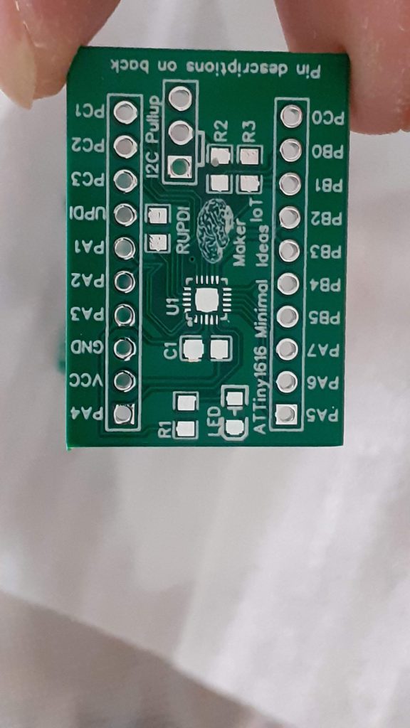
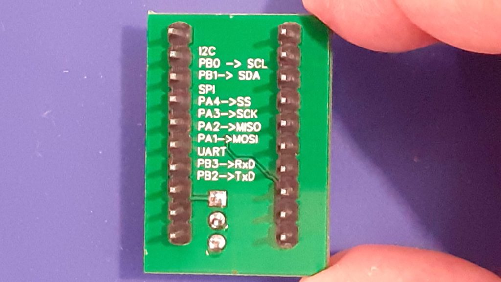 ATTiny 1616 Breakout – Bottom view
The PCB – Minimal working configuration – with a few extras
The PCB break-out all 18 of the GPIO pins, while it is only recommended to use 17 of them, unless, like in the case of the ATTiny202, you have access to an HV UPDI programmer. It also becomes possible, although still being quite tedious and awkward, to use the OptiBoot Bootloader on this chip, although it is still not quite recommended. Just using a UPDI programmer, with a separate USB-to-Serial adapter on another port is still definitely the easiest.
The Board contains an LED, on PIN_PA4, Arduino Pin 16, as well as onboard I2C pull-up resistors, selectable via a jumper. It is important to note that the current version DOES NOT contain a voltage regulator on the PCB. It is up to you to provide a regulated voltage source, in the range of 1.8v to 5.5v DC
It is recommended to clock the Chip at 16MHz when running at 5v ( 20Mhz is possible, But I did not bother to test that yet)
8Mhz when running at 3.3v
0-5Mhz when running at 1.8v
See the Datasheet, as well as the megaTinyCore documentation for exact details on this.
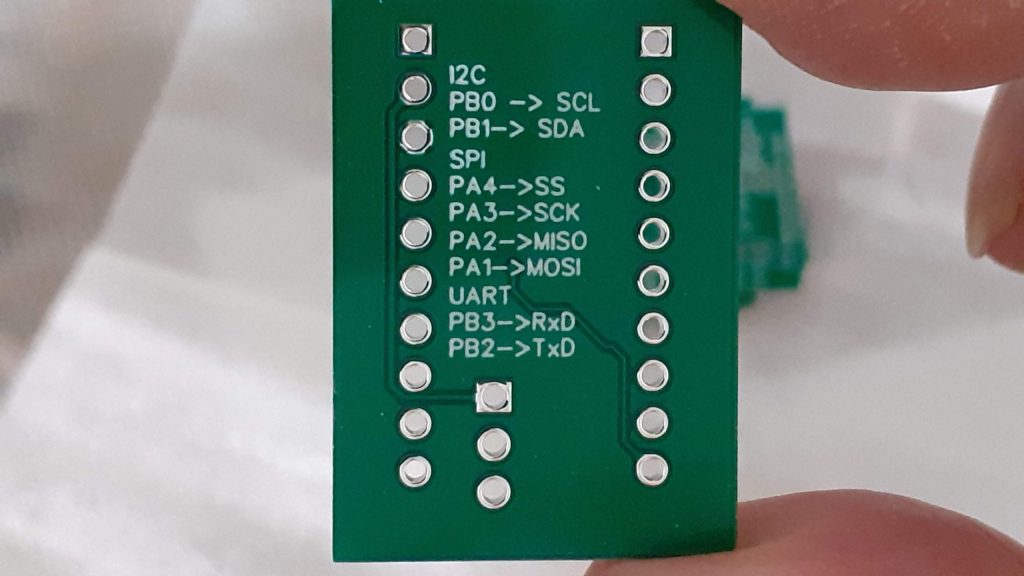
Commonly used peripherals, by myself, are listed on the back of the PCB for easy reference.
Programming the board
Programming is possible with Arduino IDE (and platformIO, ( I didn’t test that, as I find VS-Code tedious to use ), as well as MPLab from Microchip.
For the Arduino IDE, you have to install the megaTinyCore Arduino Core, as already mentioned above. ( This also apparently works for PlatformIO)
Full instructions, as well as some very useful other tips and information, is available in the core documentation, so do put in the effort to actually read the documentation. You won’t be sorry that you did.
The Schematic
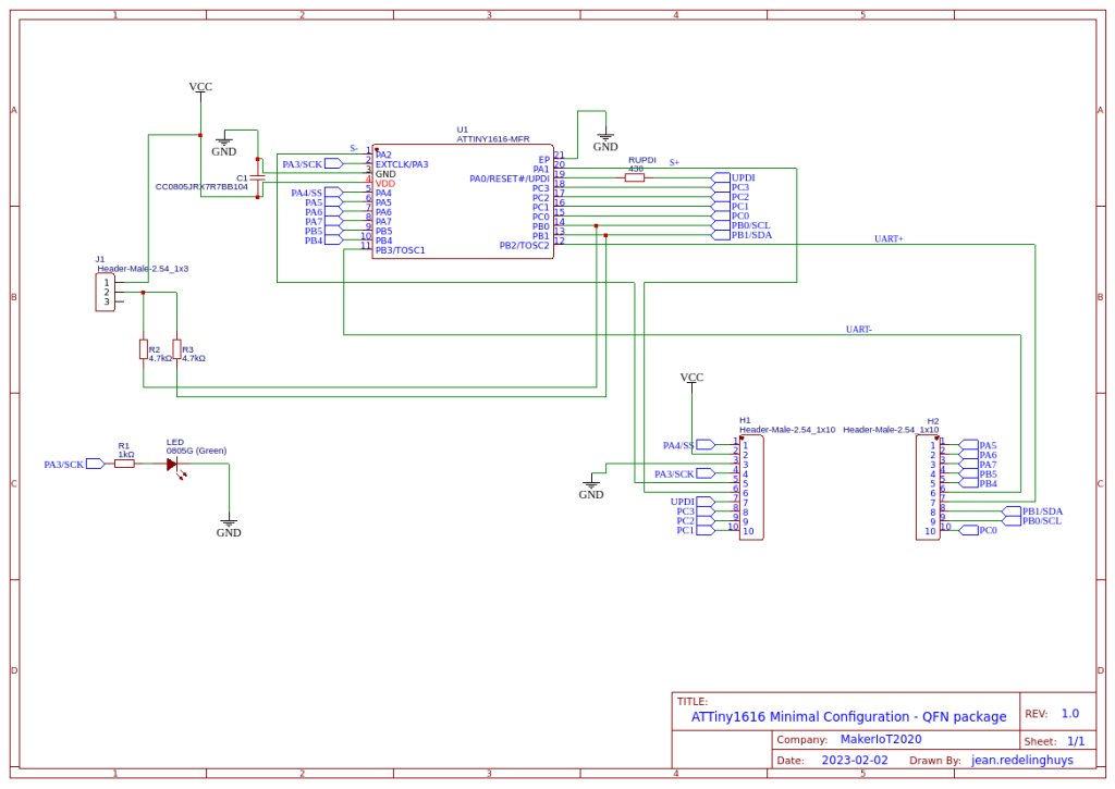 Schematic
Design and Assembly
 PCB layout
The board is designed as a double-layer PCB, with ground planes on both sides.
Due to the MCU package having a QFN footprint, using a proper SMD stencil is strongly recommended.
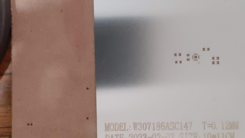 SMD Stencil – Make things a bit easier.
Hot-Air or a hotplate will also be quite useful to ensure success with this project. Passive components can be hand soldered though.
Picture Gallery
 PCB Top
 PCB Bottom
PCB Top – Assembled
PCB Bottom – Assembled
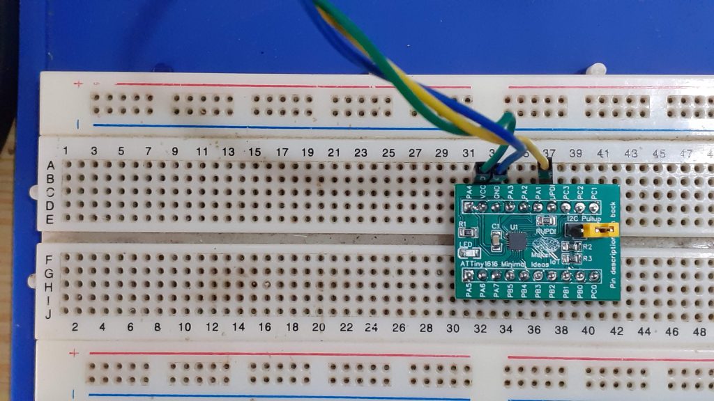 ATTiny1616 Breakout on breadboard
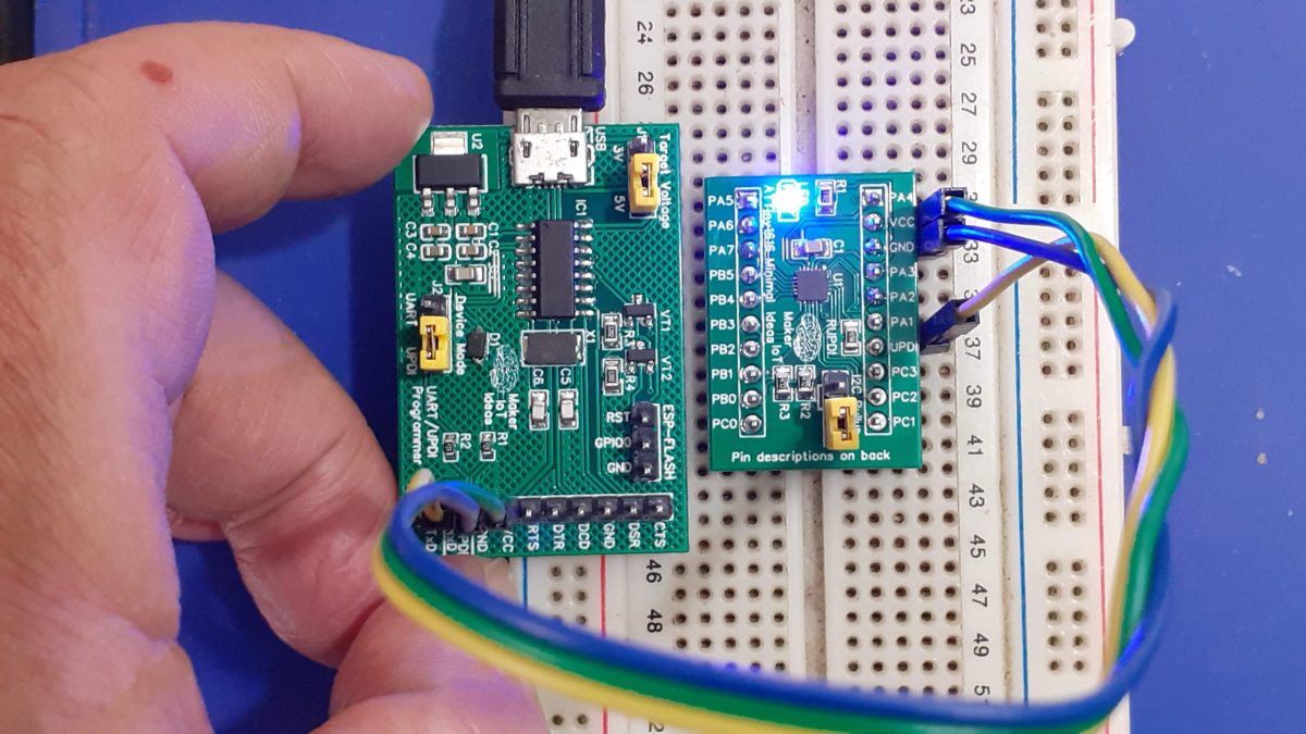
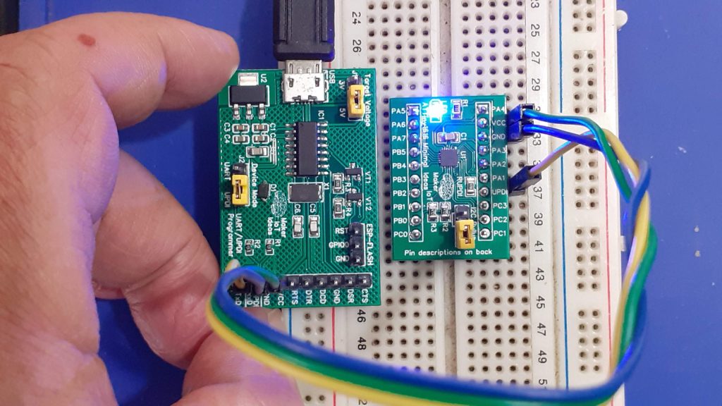 ATTiny1616 Breakout, with MakerIoT Multipurpose UPDI Progammer on Breadboard, running blink sketch
/*
    This is the standard Arduino Blink Sketch.
    It has been modified to toggle the correct pin,
    in this case PIN_PA3, or Arduino Pin 16

    Note that you HAVE TO install the megaTinyCore Arduino core
    from here:
    https://github.com/SpenceKonde/megaTinyCore/blob/master/megaavr/extras/ATtiny_x16.md

    BEFORE trying to flash code to the ATTiny1616 using the Arduino IDE.
    See installation instructions for the core at the GitHub page.

    You will also need a UPDI programmer. A Serial USB-to-UART WILL NOT WORK

*/

void setup()
{

  pinMode(16, OUTPUT);
}


void loop()
{
  digitalWrite(16, HIGH);   // turn the LED on (HIGH is the voltage level)
  delay(1000);                       // wait for a second
  digitalWrite(16, LOW);    // turn the LED off by making the voltage LOW
  delay(1000);                       // wait for a second
}

ATTiny1616 Minimal Breakout board - QFN
*PCBWay community is a sharing platform. We are not responsible for any design issues and parameter issues (board thickness, surface finish, etc.) you choose.


Raspberry Pi 5 7 Inch Touch Screen IPS 1024x600 HD LCD HDMI-compatible Display for RPI 4B 3B+ OPI 5 AIDA64 PC Secondary Screen(Without Speaker)
BUY NOW


- Comments(1)
- Likes(0)
More by Jean Redelinghuys MakerIoT2020
-
 PCB_MCP23008_2023-10-08
MCP23008 BreakoutI designed this breakout to assist me during prototyping my next version of the “RP...
PCB_MCP23008_2023-10-08
MCP23008 BreakoutI designed this breakout to assist me during prototyping my next version of the “RP...
-
 PCB_XiaoRP2040-Mouse-REV2
Xiao RP2040 Joystick Mouse – revision 2.00Revision 1.0 of the ProjectOver the last few months, I hav...
PCB_XiaoRP2040-Mouse-REV2
Xiao RP2040 Joystick Mouse – revision 2.00Revision 1.0 of the ProjectOver the last few months, I hav...
-
 Multi Purpose IO Card
Multi-Purpose IO CardWhen we are working on a prototype, we always need access to pushbuttons, encod...
Multi Purpose IO Card
Multi-Purpose IO CardWhen we are working on a prototype, we always need access to pushbuttons, encod...
-
 Variable Voltage Power Module
Powering electronics projects are always challenging. This Variable vol...
Variable Voltage Power Module
Variable Voltage Power ModulePowering electronics projects are always challenging. This Variable vol...
-
 I2C Matrix Keypad
An I2C Matrix KeypadThe completed I2C Matrix KeypadIn a previous post this month I introduced my 4×4...
I2C Matrix Keypad
An I2C Matrix KeypadThe completed I2C Matrix KeypadIn a previous post this month I introduced my 4×4...
-
 ESP32-S Development Board, in "Arduino Uno" form factor
UPDATE 24/06/2023:This board now has a Hardware Revision 2.0 available. It is the same board but wit...
ESP32-S Development Board, in "Arduino Uno" form factor
UPDATE 24/06/2023:This board now has a Hardware Revision 2.0 available. It is the same board but wit...
-
 W307186ASC94_Gerber_PCB_USB-Ports
USB Power Supply ModuleUSB Ports are quite handy to power all our day-to-day electronic devices, but...
W307186ASC94_Gerber_PCB_USB-Ports
USB Power Supply ModuleUSB Ports are quite handy to power all our day-to-day electronic devices, but...
-
 Atmega 328P based PWM controller Card
ATMega 328P Based PWM controller CardAs part of my recent ESP-12E I2C Base Board project, I designed...
Atmega 328P based PWM controller Card
ATMega 328P Based PWM controller CardAs part of my recent ESP-12E I2C Base Board project, I designed...
-
 W307186ASC71_Gerber_PCB_ESP-Now Remote
Today we will look at the remote control unit for the Robotic Toy Car – Part 6.The project is close ...
W307186ASC71_Gerber_PCB_ESP-Now Remote
Today we will look at the remote control unit for the Robotic Toy Car – Part 6.The project is close ...
-
 W307186ASV69_Gerber_PCB_Robot-Car-MCU-Board Prototype
In our last project, we started working on repurposing an old toy car. In this part, Robot Toy Car –...
W307186ASV69_Gerber_PCB_Robot-Car-MCU-Board Prototype
In our last project, we started working on repurposing an old toy car. In this part, Robot Toy Car –...
-
 W307186ASV62_Gerber_PCB_DUAL-H-Bridge
by makeriot2020 on May 27, 2022Many of us have old toys laying around the house, they belong to ou...
W307186ASV62_Gerber_PCB_DUAL-H-Bridge
by makeriot2020 on May 27, 2022Many of us have old toys laying around the house, they belong to ou...
-
 CAN-BUS Breakout
Breadboard Compatible CAN-BUS Breakout ModuleWhat is this:Some of us have already used the commonly ...
CAN-BUS Breakout
Breadboard Compatible CAN-BUS Breakout ModuleWhat is this:Some of us have already used the commonly ...
-
 RA-02 Breakout with Level converters
Breadboard and beginner-friendly RA-02 Breakout ModuleMost Makers and electronics enthusiasts may al...
RA-02 Breakout with Level converters
Breadboard and beginner-friendly RA-02 Breakout ModuleMost Makers and electronics enthusiasts may al...
-
 ATMEGA328P Module with integrated LoRa and CAN Bus
ATMEGA328P Module with integrated LoRa and CAN-BUSINTRODUCTIONIn my quest to perfect my LoRa telemet...
ATMEGA328P Module with integrated LoRa and CAN Bus
ATMEGA328P Module with integrated LoRa and CAN-BUSINTRODUCTIONIn my quest to perfect my LoRa telemet...
-
 Sx127x-Ra-02-Test-Module with ATMEGA328P-AU
SX127x LoRa/FSK/OOK Prototype Radio BoardI recently had a requirement to do some automation/telemetr...
Sx127x-Ra-02-Test-Module with ATMEGA328P-AU
SX127x LoRa/FSK/OOK Prototype Radio BoardI recently had a requirement to do some automation/telemetr...
-
 USB-ASP Programmer ATMEGA8
Build your own USB-ASP Programmer CloneBymakeriot2020 FEB 21, 2022 Arduino, ASP programmerUsing mor...
USB-ASP Programmer ATMEGA8
Build your own USB-ASP Programmer CloneBymakeriot2020 FEB 21, 2022 Arduino, ASP programmerUsing mor...
-
 ATTiny1616-LIGHT-Controller-with-CAN_B_PCB_ATTiny1616-LIGHT-Controller-with-C_2024-09-11
Assembly of the ATTiny1616 Can bus controller PCBThe Assembly of the ATTiny1616 Can Bus Controller P...
ATTiny1616-LIGHT-Controller-with-CAN_B_PCB_ATTiny1616-LIGHT-Controller-with-C_2024-09-11
Assembly of the ATTiny1616 Can bus controller PCBThe Assembly of the ATTiny1616 Can Bus Controller P...
-
 ATTiny1616QFN-CAN-Remote-Neopixel-Ligh_PCB_ATTiny1616QFN-CAN-Remote-Neopixel-2024-09-11_2024-09-11
NeoPixel CAN-Bus Module with local controlAs part of my current project to add NeoPixels to the cabi...
ATTiny1616QFN-CAN-Remote-Neopixel-Ligh_PCB_ATTiny1616QFN-CAN-Remote-Neopixel-2024-09-11_2024-09-11
NeoPixel CAN-Bus Module with local controlAs part of my current project to add NeoPixels to the cabi...
-
Programmable Mist Maker - XIAO / QT PY Extension
479 1 0 -
RadioHAT - Raspberry Pi radio development platform
381 0 1 -
-
-
-
-
ARPS-2 – Arduino-Compatible Robot Project Shield for Arduino UNO
2914 0 6 -
A Compact Charging Breakout Board For Waveshare ESP32-C3
3418 3 8 -
AI-driven LoRa & LLM-enabled Kiosk & Food Delivery System
3758 2 2


