Simple microphone preamplifier
Summary of circuit features
- Brief descript_ion of operation: Simple microphone preamplifier
- Circuit protection: No special protection circuits used
- Circuit complexity: Very simple one transistor circuit
- Circuit performance: Amplification 35 dB, flat frequency response from 20 Hz to 20 kHz, quite poor distortion performance figures, a little bit noisy
- Availability of components: Uses common and easily available components
- Design testing: I have built few microphone preamplifiers based on this circuit and theu have worked without problems.
- Applications: Interface dynamic or electret microphone to a line level audio input in HIFI amplifier or computer soundcard.
- Power supply: 9V battery, takes less than 10 mA current
Circuit descript_ion
This is a simple microphone preamplifier circuit which you can use between your microphone and stereo amplifier. This circuit amplifier microphone suitable for use with normal home stereo amplifier line/CD/aux/tape inputs. This microphone preamplifier can take both dynamic and electret microphone inputs (preamplifier provides power foe electret microphone elements). The idea of this circuit is to keep the design as simple as possible to be easy to build. That was my goal when I needed a simple external microphone preamplifier for my mixer. The performance of the circuit is nothing superior but can be used with many not so serious projects.
The circuit is a simple one transistor amplifier with amplification of about 30-40 dB (depends on transitor, temperature and voltage). The dynamic mic input is just a simple one transistor amplifier circuit with nothing special in it. LED D1 is in the circuit to show that the circuit operates. The voltage drop caused by LED (around 1.8V for RED led) has been taten in account when designing the amplifier circuit built around Q1. Resistor R4 and capacitor C5 make a filter to filter out possible noise from battery or other power source which is used to feed this circuit. Capacitors C1, C2 and C3 are used to block the DC bias on Q1 base to flow out of microphone input to microphone (the polarity of all capactors is straigh line = + and curved line = -).
Electret microphone input has a resistor R1 fo feeding current through electret microphone capsule when it is connected to the electret microphone input. Electret microphone needs some current (about 1 mA) flowing through it to operate, because there is a small amplifier circuit inside the microphone capsule. This circuit is suitable for all typical cheap electret capsules which available from any electronic component shop. Because electret microphones have higher signal level output, it is quite easy to overdrive the amplifier when you shout to electret microphone.
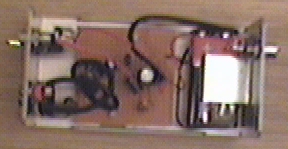
The circuit is bet to build to a small metal box like in the picture above. Put the 9V battery inside the case too. Battery power and metal box keep external noise and interference sources away. I used standard 6.3 mm jack for dynamic microphone and 3.5 mm mono jack for electret micrphone both installed to from, panel of the metal box. The LED and power switches are also installed to front panel.
Measured specifications from protype
- Frequency response: 20 Hz to 20 kHz +-1dB
- Noise level (A-weighted): -85 dBm
- Amplification: 35 dB
Because of the simplicity of the design the distortion performance is not very good. At signal levels typically used by electret microphones the distortion is about 2-3%. With dynamic microphones the distortion level is lower (not measured). Here is the frequency response as measured by LoudSpeaker LAB software DEMO version with Sound Blaster 16 PNP card:
The bass frequency attenuation is caused by the microphone preamplifier circuit. The high end attenuation is caused by Sound Blaster 16 card. As seen in the measured performance, the microphone preamplifier is suitable for speaker measurements made using suitable measurement software and sound card. Using this preamplifier connected to line level input the problems caused by poor microphone preamplifier in many sound cards can be avoided.
Component list
R1      4.7 kohm
R2      220 kohm
R3      2.2 kohm
R4      120 ohm
C1..C4  10 uF 16V electrolytic
C5      100 uF 16V electrolytic
D1      Red LED
Q1      BC547B
SW1     on/off switch