


![IMG_20240112_080141[1].jpg](https://pcbwayfile.s3.us-west-2.amazonaws.com/web/24/01/12/1215272081883m.jpg)

|
arduino IDEArduino
|
|

|
MIT App InventorMIT
|
|

|
Visual Studio Code |
|
|
|
Tim's PCA9685 ControllerTim
|
|

|
fritzing |
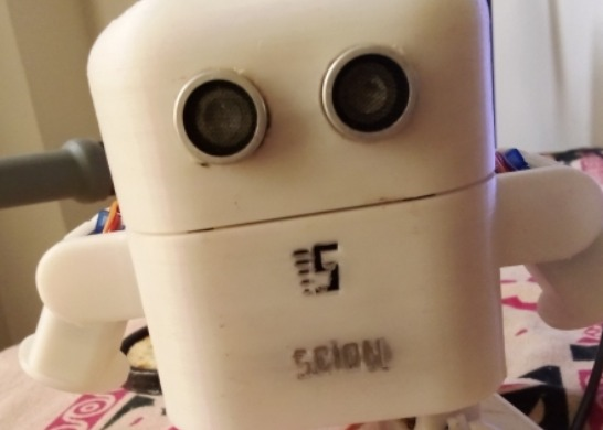
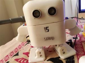
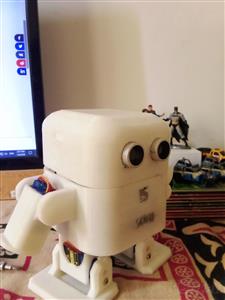
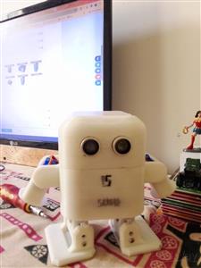
Scion V1 - Semi Autonomous Bluetooth Controllable Robot With ESP32 and PCA9685 Servo Driver
This robot was inspired by OTTO Humanoid and the bodywork is bought from Scion Electronics and links are in my GitHub repostiory. Here's what I used:
1x DOIT ESP32 DEVKIT V1 - https://alphatronic.lk/product/esp32-development-board/
1x PCA9685 Servo Driver - https://alphatronic.lk/product/16-channel-pwm-servo-controller-module/
1x HC-SR04 Ultrasonic Sensor - https://alphatronic.lk/product/hc-sr04-ultrasonic-sensor-module/
6x Tower Pro SG90 Servos - https://alphatronic.lk/product/tower-pro-micro-servo-9g/
3x Li-Po Batteries - https://alphatronic.lk/product/lipo-battery-3-7v-600mah/
1x LM2596 Step Down Converter - https://alphatronic.lk/product/lm2596-dc-to-dc-step-down-buck-adjustable-module/
1X IR Obstacle Avoiding Module - https://alphatronic.lk/product/infrared-obstacle-avoidance-sensor-module/
Female to Female Jumper Wires as needed - https://alphatronic.lk/product/jumper-wire-female-female/
The Body - https://scionelectronics.com/product/3d-printed-otto-robot-with-arms-made-in-sl/
The 3D Files from - https://www.printables.com/model/225220-bobotto-the-humanoid-robot
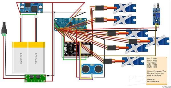
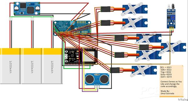
The Circuit Diagram:

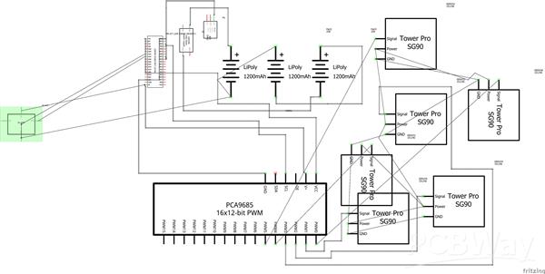
The schematic:
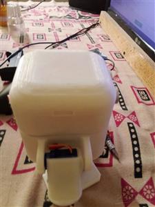
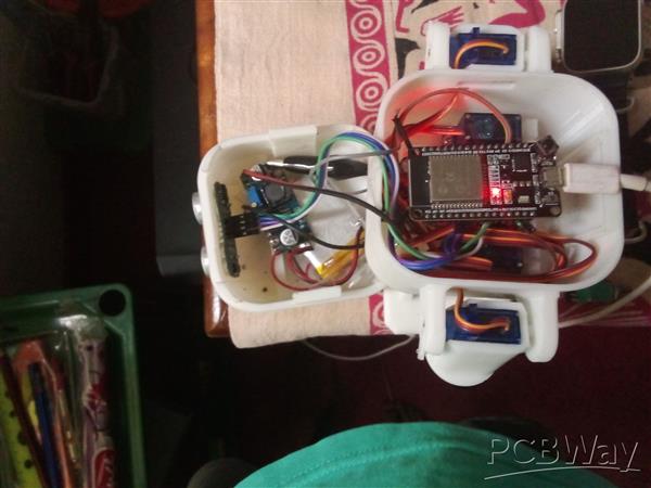
A look from the inside :
Warning! Please make sure that Step-Down Converter outputs 5V or it'll wreak havoc!
The 3D files aren't the same as used ones in the project, but it can be used just fine.
Here's the circuit diagram if you want to use an integrated charger:
If you print the 3D files here're the quantities:
1x Head.stl
1x Body.stl
2x Leg.stl
2x Arm.stl
2x Foot.stl
A simple tutorial can be downloaded from the link at downloads.
Also learn more from here : https://www.instructables.com/Scion-V1-Semi-Autonomous-Bluetooth-Controllable-Ro/
A big thank for my friend Nileesha Thatsasra who helped me for this project with electronics, ideas and importantly courage.Thanks a lot for the help!
#include <Wire.h>
#include <BluetoothSerial.h>
#include <Adafruit_PWMServoDriver.h>
#include <NewPingESP8266.h>

Adafruit_PWMServoDriver pwm = Adafruit_PWMServoDriver();
BluetoothSerial SerialBT;

#define SENSOR_PIN 19
#define trig_pin 32
#define echo_pin 33
#define maximum_distance 200

NewPingESP8266 sonar(trig_pin, echo_pin, maximum_distance);

int state = digitalRead(SENSOR_PIN);
int pos0 = 150;
int pos180 = 520;
int buzzer = 18;
int distance = 100;

void setup() {
  pinMode(buzzer, OUTPUT);
  pinMode(SENSOR_PIN, INPUT);
  Serial.begin(115200);
  SerialBT.begin("Scion V1 Robot");
  Serial.println("Scion V1 Robot.");
  pwm.begin();
  pwm.setPWMFreq(50);
  digitalWrite(buzzer, HIGH);
  delay(1000);
  idle_pos();
  distance = sonar.ping_cm();
  delay(30);
  distance = sonar.ping_cm();
  delay(30);
  distance = sonar.ping_cm();
  delay(30);
  distance = sonar.ping_cm();
  delay(30);
}

void setServo(int servo, int angle) {
  int duty;
  duty = map(angle, 0, 180, pos0, pos180);
  pwm.setPWM(servo, 0, duty);
}

void idle_pos(){
  setServo(0, 90);
  setServo(1, 90);
  setServo(2, 90);
  setServo(3, 90);
  setServo(4, 180);
  setServo(5, 180);
}

void Forward() {
  setServo(0, 60);
  setServo(1, 120);
  setServo(2, 70);
  setServo(3, 110);
  setServo(4, 180);
  setServo(5, 180);
  delay(200);
  setServo(0, 90);
  setServo(1, 90);
  setServo(2, 90);
  setServo(3, 90);
  setServo(4, 180);
  setServo(5, 180);
  delay(200);
}

void Backward() {
  setServo(0, 120);
  setServo(1, 60);
  setServo(2, 110);
  setServo(3, 70);
  setServo(4, 180);
  setServo(5, 180);
  delay(200);
  setServo(0, 90);
  setServo(1, 90);
  setServo(2, 90);
  setServo(3, 90);
  setServo(4, 180);
  setServo(5, 180);
  delay(200);
}

void Stop() {
  setServo(0, 90);
  setServo(1, 90);
  setServo(2, 90);
  setServo(3, 90);
  setServo(4, 180);
  setServo(5, 180);
}

void Left() {
  setServo(0, 60);
  setServo(1, 60);
  setServo(2, 70);
  setServo(3, 70);
  setServo(4, 180);
  setServo(5, 90);
  delay(200);
  setServo(0, 90);
  setServo(1, 90);
  setServo(2, 90);
  setServo(3, 90);
  setServo(4, 180);
  setServo(5, 90);
  delay(200);
}

void Right() {
  setServo(0, 120);
  setServo(1, 120);
  setServo(2, 110);
  setServo(3, 110);
  setServo(4, 90);
  setServo(5, 180);
  delay(200);
  setServo(0, 90);
  setServo(1, 90);
  setServo(2, 90);
  setServo(3, 90);
  setServo(4, 90);
  setServo(5, 180);
  delay(200);
}

void Hands_up() {
  setServo(4, 0);
  setServo(5, 0);
}

void hand_dance() {
  setServo(4, 180);
  setServo(5 ,0);
  delay(350);
  setServo(4, 0);
  setServo(5, 180);
  delay(350);
  setServo(4, 90);
  setServo(5, 90);
  delay(350);
  setServo(4, 180);
  setServo(5, 180);
  delay(350);
  setServo(4, 0);
  setServo(5, 0);
  delay(350);
  setServo(4, 0);
  setServo(5 ,180);
  delay(350);
  setServo(4, 180);
  setServo(5, 0);
  delay(350);
  setServo(4, 90);
  setServo(5, 90);
  delay(350);
  setServo(4, 180);
  setServo(5, 180);
  delay(350);
}

void Small_stop() {
  setServo(0, 90);
  setServo(1, 90);
  setServo(2, 90);
  setServo(3, 90);
  setServo(4, 180);
  setServo(5, 180);
  delay(1500);
}

void Semi_auto() {
  setServo(0, 120);
  setServo(1, 60);
  setServo(2, 110);
  setServo(3, 70);
  setServo(4, 160);
  setServo(5, 160);
  digitalWrite(buzzer, HIGH);
  delay(300);
  setServo(0, 90);
  setServo(1, 90);
  setServo(2, 90);
  setServo(3, 90);
  setServo(4, 160);
  setServo(5, 160);
  digitalWrite(buzzer, LOW);
  delay(300);
}

void Semi_auto2() {
   setServo(0, 60);
  setServo(1, 120);
  setServo(2, 70);
  setServo(3, 110);
  setServo(4, 160);
  setServo(5, 160);
  digitalWrite(buzzer, HIGH);
  delay(300);
  setServo(0, 90);
  setServo(1, 90);
  setServo(2, 90);
  setServo(3, 90);
  setServo(4, 160);
  setServo(5, 160);
  digitalWrite(buzzer, LOW);
  delay(300);
}

void loop() {
  distance = sonar.ping_cm();
  delay(30);
  if (SerialBT.available() > 0) {
    char value = SerialBT.read();
    Serial.println(value);

    if (value == 'U') {
      Forward();
    }
    else if (value == 'D') {
      Backward();
    }
    else if (value == 'S') {
      Stop();
    }
    else if(value == 'L'){
      Right();
    }
    else if(value == 'R'){
      Left();
    }
    else if(value == '1'){
      Hands_up();

    }
    else if(value == '2'){
      idle_pos();

    }
    else if(value == '3') {
      hand_dance();

    }
    else if(value == '4') {
      Small_stop();

    }
  }
   else if(distance <= 7) {
    Semi_auto();
   }
   else if(state == HIGH) {
    Semi_auto2();
   }
  }

Scion V1 - Semi Autonomous Bluetooth Controllable Robot With ESP32 and PCA9685 Servo Driver
*PCBWay community is a sharing platform. We are not responsible for any design issues and parameter issues (board thickness, surface finish, etc.) you choose.


Raspberry Pi 5 7 Inch Touch Screen IPS 1024x600 HD LCD HDMI-compatible Display for RPI 4B 3B+ OPI 5 AIDA64 PC Secondary Screen(Without Speaker)
BUY NOW


- Comments(3)
- Likes(9)
- 9 USER VOTES
- YOUR VOTE 0.00 0.00

-
9design
-
7usability
-
9creativity
-
7content

-
9design
-
10usability
-
8creativity
-
10content
-
10design
-
9usability
-
10creativity
-
10content
-
9design
-
9usability
-
9creativity
-
8content

-
3design
-
4usability
-
6creativity
-
8content
-
7design
-
6usability
-
7creativity
-
6content
-
9design
-
8usability
-
9creativity
-
9content
-
10design
-
10usability
-
8creativity
-
10content
-
9design
-
8usability
-
8creativity
-
10content
More by Dinul Sasnada
-
 Scion V1 - Semi Autonomous Bluetooth Controllable Robot With ESP32 and PCA9685 Servo Driver
This robot was inspired by OTTO Humanoid and the bodywork is bought from Scion Electronics and links...
Scion V1 - Semi Autonomous Bluetooth Controllable Robot With ESP32 and PCA9685 Servo Driver
This robot was inspired by OTTO Humanoid and the bodywork is bought from Scion Electronics and links...
-
 ESP32-WROOM-IE Dev Board
This board is a small form factor ESP32 board that supports all the ESP32 shields. It is one of the ...
ESP32-WROOM-IE Dev Board
This board is a small form factor ESP32 board that supports all the ESP32 shields. It is one of the ...
-
 Dev Board for OpenCat Project
This project is designed to use for robotic purposes and based on Arduino Uno with extra features. T...
Dev Board for OpenCat Project
This project is designed to use for robotic purposes and based on Arduino Uno with extra features. T...
-
Programmable Mist Maker - XIAO / QT PY Extension
80 0 0 -
RadioHAT - Raspberry Pi radio development platform
101 0 0 -
-
-
-
-
ARPS-2 – Arduino-Compatible Robot Project Shield for Arduino UNO
2722 0 5 -
A Compact Charging Breakout Board For Waveshare ESP32-C3
3220 3 8 -
AI-driven LoRa & LLM-enabled Kiosk & Food Delivery System
3476 2 2


