|
Autodesk Fusion 360Autodesk
|
|

|
Ultimaker CURA |
Helical Antenna for GOES/GK-2A weather satellite reception.
General Theory:
Usually when someone thinks about satellite communication first thing that comes to mind is the star-link constellation which was launched by SpaceX, but satellites are not just used for providing the internet but also for various other purposes. One of the uses of a satellite is monitoring weather, and since weather is accessible to everyone, in general, these weather satellites broadcast data that can be accessible by everyone, and anyone with appropriate tools can capture these signals and decode them.
Weather satellites are mostly of 2 different categories, Polar-orbiting satellites (orbiting from earth’s pole to pole) and Geostationary satellites. Polar-orbiting satellites are in lower earth orbit and are sun-synchronous, which means their position with respect to the sun remains constant, as a result, they revolve around the earth with the sun's position locked with respect to the satellite. Polar-orbiting satellites are much closer to the earth's surface and the images they capture are panoramic. Secondly, since they are sun-synchronous, the time of their rise and set is mostly the same every day. The second advantage of the polar-orbiting satellite is that since these satellites are much closer to the earth's surface, the signal that they broadcast is very strong and anyone with a simple software-defined radio and a dipole antenna can capture it.
The second type of weather satellite is Geo stationary and as the name suggests these satellites are locked with respect to the earth's surface and anyone within the range of these satellites can capture the signals. Since the geo stationary orbit lies at around 36000 KM above the earth's surface, these satellites are way far compared to polar-orbiting satellites and require some special equipment along with the software-defined radio. A satellite TV dish (80 cm to 1 mt in diameter) and a low-noise amplifier are used along with the software-defined radio to capture geostationary satellite signals.

Signal Processing:
Now let’s discuss how one can capture the signals from these geo-stationary satellites. Before the digital era, most satellites usually broadcast analog signals either AM or FM signal, and that too in UHF or VHF band (UHF – Ultra High Frequency around 300 MHz, VHF – Very High Frequency around 100 MHz). If you were born in the 1980s or 1990 then you might have seen large dishes installed above the houses that were responsible for capturing these analog signals and then amplifying and re-distributing them to nearby houses.

But with the rise of modern computers and advanced mobile devices, even satellite broadcasting was digitalized. If you remember in the early 2000s, we used to hear about DTH services which are capable of transmitting HD-quality video directly to our houses without static noise. This was possible with the help of digitalizing satellite broadcasts. This digitalizing of satellite signals is known as DVB or Digital Video Broadcast and the technology that DVB uses is known as BPSK (Binary Phase Shift Keying) or QPSK (Quadrature Phase Shift Keying). We will discuss BPSK and QPSK later. DVB is mostly used by TV satellites, but the BPSK and QPSK exist behind every form of radio communication including weather satellites, deep space communication, Wi-Fi, Bluetooth, or any form of GSM service (3G, 4G, or 5G).
As the name suggests PSK stands for Phase shift keying, and unlike FM where the Frequency of a radio signal is modulated, or AM where the Amplitude is modulated, in PSK phase of the signal is modulated. You might ask, what benefit that we get in the modulating phase? The answer is, in this universe whenever an electromagnetic source emits an electromagnetic wave (including light), with time noise can be introduced in the signal that can modify the wave frequency (aka redshift, or Dopplers effect) or the amplitude, but the phase of the wave can not be altered, so PSK (either BPSK or QPSK) can be used for very long range communication.
The concept of BPSK is very simple, if we plot a radio signal on a graph with phase on X-axis and amplitude on Y axis, then at a time the signal that a receiver receives can have phase either in sin or cos, let us assume sin is negative x-axis and cos is positive x-axis then a constellation diagram can be plotted that look like below diagram.

Here sharper the constellation better the signal quality. Once the signal is received in the BPSK, the signal processor will consider the negative values as 0 and the positive values as 1, and finally receive the signal in the form of a stream of 0s and 1s. There is one more thing that the receiver must figure out which is the bit rate (commonly known as a sample rate), or the speed at which the phase is shifted, once this rate has been determined the signal can be decoded into useful data. As soon as the bit rate is determined, we can say the signal is locked and data has started streaming. If you use any generic tool to decode these satellite data, you will always see that the receiver will try to lock on to the signal, and it will print a message that the signal is locked.
One thing that we should notice is that if we want to increase the speed of the data we receive, then we can do 2 things, either we increase the sample rate of the signal or instead of 2 constellations we can generate 4, 8, or 16 (till 2^n) constellations, and individual constellation can represent 0, 1, 2, 3…. and so on. Hence bigger byte can be transferred at a time. To generate 4 or more constellations, the amplitude of the signal should also be modulated. That is what QPSK does. QPSK has 4 constellations as shown below.

Few weather satellites such as Fengyun 4b, which is a Chinese weather satellite, use higher sample rates and are hence capable of broadcasting at higher speeds. But remember sample rate depends on the radio receiver, unlike BPSK or QPSK, which requires only software manipulation to receive the data at higher speed.

SDR (Software Defined Radio)

Today in the market there are various Software-defined radios are available including the most famous RTL-SDR V3, which we are going to use in this project. But let’s try to understand what a software-defined radio is. As we have studied in basic electronics, a radio signal consists of 2 things, one is the carrier wave and the second is the signal. The concept of QPSK and BPSK, or even FM or AM comes into the picture once the signal is separated from the carrier wave. This signal is then demodulated into useful data either into an audio signal or digital data. This is what a software-defined radio does, it is responsible for separating the signal from the carrier wave. One might ask, why don’t we feed the entire signal to the signal processor (usually a computer connected to an SDR), and let it process everything, but the problem is that the signal that these weather satellite broadcasts are in the frequency of 1-2 GHz, and in order to process such a high-frequency signal, lots of CPU power will be consumed, and the data that flow between an SDR and the PC will be too high to be handled by any kind of USB device. In short, a software-defined radio first brings down the high radio frequency to lower frequencies by using frequency mixers and then separates out the signal from the carrier wave and passes it on to a Signal Processor or a PC. That’s why if you open an SDR dongle you will see major 2 ICs, one for shifting the radio frequency to a lower value and the other one for separating out the signal from the carrier wave.

A fun fact about these SDRs is that these devices were never intended to be used to scan radio signals, instead, they were originally called TV tuner cards, if you were born in the 90s, you might have heard about these TV tuner cards, we use to have in our computers in order to watch TV broadcasts on our PC, but then some hackers figure out that the frequency range on these TV tuner cards are just restricted by the driver software and one can write custom driver in order to access the full capability of these TV tuner cards and further turning them into Software Defined Radios. That’s why if you plug in the RTL-SDR dongle for the first time into your PC, you have to use software such as Zadig, to replace the default driver with this hacked driver.
Other Components:
Before coming to the main part of this project, which is a helical antenna, let's quickly walk through some other components that we need to fetch weather satellite signals. Along with a software-defined radio, we need an LNA (Low Noise Amplifier) and a Dish. A low noise amplifier is an RF amplifier that amplifies the low RF signals and feeds them to the Software Defined Radio. In this project, we will be using a SAWBird filter + LNA from Nooelec which is a combination of an RF amplifier and a bandpass filter. A bandpass filter basically filters out any unwanted frequency and only allows the frequency that is in range of these weather satellites. There are various LNAs available from Nooelec and the one we need is for the GOES satellite, whose center frequency is 1.688 GHz and allows 80 Mhz above and below the center frequency.

Almost every weather satellite can be covered with the help of this LNA except one from India which is INSAT 3D, which broadcasts signals around 4.7 GHz. The second component that we want is a dish antenna. As I have already discussed above, in the case of a polar-orbiting satellite, we only require a dipole antenna, which is sufficient to capture the satellite signals, but in the case of geo stationary satellite, we require a dish, which acts as a parabolic mirror to concentrate the signals from these satellite to the focal point where our helical antenna will sit. Here we must remember that the bigger the dish better the signal strength but remember there is a lower limit to the size of the dish. Usually higher the radio frequency, the smaller the dish we can use to capture the signal. That’s why DTH dishes are very small in size usually 45 cm, because the frequency at which the TV broadcasts work is in the KU band i.e.,10 – 11 GHz. But in our case, the signal is in 1-2 GHz so the minimum size of the dish should be at least 80 cm, but the best will be around 100 cm in dia.
Can you guess why, unlike TV broadcasts, weather satellites do not operate in the KU band which is in the range of 10-11 GHz, since all the components are readily available in the market at a cheaper cost? The answer is quite simple i.e., the signal in the KU band will get blocked by the thick clouds and the ground stations will not be able to receive the signals from these weather satellites, though the use of these satellites is mostly in bad weather conditions. Hence these weather satellites along with some other communications satellites for emergency purpose such as the Inmarsat and Iridium satellite constellation operates in the L band which is between 1-2 GHz. The best part about L Band frequency is that it can pass through thick clouds and is still very directional which means it can travel 36000 Kilometers without losing much power. However, there is one drawback of L band frequency that we will discuss in the next section.
LNB (Low noise block, downconverters)

Although we are not going to use this component in our project, it is very important to understand about LNBs and the benefits that we get from such devices. That is how we will be able to understand a few challenges that we have to face in our setup. First of all, why we are not using LNBs in our project, they look so cute like a microphone and personally they always fascinated me since my childhood. The answer is simple, these LNBs are made for TV satellites that operate in the KU band, and the weather satellites that we are targeting operate in the L Band. These LNBs are responsible for collecting the KU band signal and then converting them 10-11 GHz to the range of 700-900 Mhz, by passing the signal through multiple frequency mixers. These LNBs have local oscillators whose values are mentioned in the specifications, and by subtracting the signal frequency from the local oscillator frequency, we can get the resultant frequency that we will receive in our radio receivers, usually a TV setup box. Why do we need to down-convert the KU band signal to the range of 700–900 MHz? Because of a phenomenon known as Link Losses. Link Loss is what we will be facing in our project.
Whenever a high-frequency signal is transmitted through a coax cable, it has been observed that after some length of wire, the power of the signal drops significantly, and the signal becomes so weak that the receiver won’t be able to detect the signal. Since in our project, we are not going to down-convert the L Band signal we must place our LNA + SDR combo as close to the antenna as possible, else the signal strength will drop significantly. Thanks to LNB, we don’t have to keep our TV setup boxes next to our TV dish, because LNBs down-convert these signals to lower frequency and amplify them, so that they can travel a significant length of wire to reach our setup boxes without losing signal.
Helical Antenna

Till now this might have been clear, that to receive the weather satellite signals, almost every component is available in the market, except one i.e., an antenna that can operate at L Band frequency. This is the prime objective of this project, to create an antenna that could be attached at the focus of the parabolic dish and can receive the signals. One might think that we can use any antenna that can be attached to the focus of the dish, and should be able to receive the signal, but the answer is NO. Because these satellites do not broadcast signals like a normal FM station, instead the signals of these weather satellites are polarized, and the antenna that we use should be made specifically for the same frequency and polarization at which the satellite broadcasts.
There are mostly 3 types of polarization, Linear Polarization, Right-Hand Circular Polarization (RHCP), and Left-Hand Circular Polarization (LHCP). The frequency and polarization of any satellite can be found on an online database (https://space.oscar.wmo.int/satellites/view/geo_kompsat_2a ).

Although polarization is a very vast topic, for simplicity we can remember this rule, an LHCP antenna will not work with RHCP signal, a RHCP antenna will not work with LHCP signal, and both LHCP and RHCP antenna will work with Linear polarized signal, but the signal strength will be reduced. Since we will be attaching our helical antenna to the focus of the dish, the linear polarized signal will be strong enough. The second thing to remember is that after reflecting from the dish, a LHCP signal will convert into an RHCP signal, and vice versa, but a linear polarized signal will remain the same. I have provided both LHCP and RHCP helical antenna designs in the project attachment, make sure you use the correct antenna with the correct type of signal, and the details about the satellite can be found on online databases. Remember if you are using a dish, make sure your antenna polarization is reverse of the broadcasting signal, except in case of linear polarization. The satellite that we are targeting in this project i.e., GK-2A has a linear polarized signal, so we can use either LHCP or RHCP antenna. Let's say you are targeting the Russian weather satellite Elektro-L N3 (https://space.oscar.wmo.int/satellites/view/electro_l_n3 ), then the signal that this satellite broadcasts is RHCP at 1691 MHz, so make sure you use LHCP antenna with the dish.
Construction:
Although the satellite antennas need to be very precise, helical antennas are a little bit forgivable when it comes to designing them. In order to calculate the spacing and the diameter of the helix one can use online calculators such as https://www.changpuak.ch/electronics/calc_12a.php. Since I have already provided the 3D print design, you can directly download the STL files and get them printed. The antenna will consist of the following components:

Component 1
A base plate, that is used to hold the ground plane made up of copper clad. By calculation, the ground plane aka the director, should be 130 mm or higher, so I have taken 135 mm dia. The best printer that will work, for such a large surface will be Ender 3.

Component 2
This part holds the copper enamel wire at the proper diameter and at the proper spacing. You can also use super glue at the holes after properly inserting the enameled copper wires.
Component 3
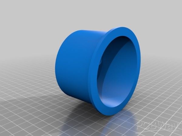
This part is used to hold the antenna at the focus and the height of this part decides how much play is available to move the antenna back and forth, to properly receive the signal.

Component 4
This part holds the antenna and provides a clamping mechanism to firmly attach the whole antenna in place of normal LNB just by a nut and bolt. This part also requires a long M3 nut along with a bolt to adjust the clamp diameter, so that it can firmly grip the antenna. In order to attach to the dish, you can use the same nut and bolt that was used to hold the original LNB.

Component 5
This part is optional, but highly recommended. This will cover the enameled copper wire helix and prevent it from any damage. Besides the 3D printed components, we also require some other materials as below:

Copper-clad or blank PCB.
We will be using this for making our ground plane and in order to add this to our antenna this copper clad needs to be cut into an appropriate size which is a disk of diameter 135 mm. First, find out the center by drawing the diagonals of the rectangular copper clad, then use a compass to draw a circle of 135 mm diameter. You can use a bench saw or as I have used a metal sheet cutter to cut it into a disk of 135 mm diameter.

Metal sheet cutter.
We also need to drill 3 holes in our copper-clad disk of the following diameter, a center hole of 10 mm diameter and 2 other holes of 10 mm and 3.5 mm diameter. The best way to trace them is to put your copper-clad disk on the 3D-printed component 1 and use a marker to mark the hole's center. Then using a drill bit of 10 mm and 3.5 mm, drill a hole in the copper-clad disk. The center hole is for a long M10 screw, that will pass from 3D print components 1, 2, and 3 to hold them together. 3.5 mm hole is for a M2 screw that will hold the copper-clad disk, and 3D-printed components 1 and 3 together.


Below is the sectional analysis of the 3, 3D printed parts that should be held together by a long M10 screw.

Sectional Analysis.

Expected assembly.

Enameled copper wire.
This enameled copper wire will be used as our helical antenna of diameter 56 mm. The thickness of this wire should be 3.5 mm in diameter. In order to bend this wire in perfect shape we can use any PVC pipe or any other cylindrical object of around 56 mm diameter and then wrap this wire around that, making in total of 5 revolutions plus some extra length for calibration which will be shortened later. Once this wire is shaped properly and cut at the appropriate length start sliding in the 2nd 3D-printed component. Since the wire is coated with enamel, it will slide very easily into the holes that are marked at the calculated distance. Once the wire reaches the copper-clad disk, its end should align the 10 mm hole's center. If not, then try to adjust the wire or the copper disk and 3D-printed component 1 orientation. Once finished the structure should look as below image.


Remember, do not cut the extra length of the enameled wire, as we might require to adjust it while soldering. The last component that we need to add to the antenna is a SMA connector, in order to attach a coax wire to our antenna.

SMA Connector.
This SMA connector needs to go to the non-centered 10 mm hole, to which we have aligned the enameled copper wires end. After inserting the SMA connector into the copper-clad disk, make sure that the SMA connector faces the fiberglass side of the copper-clad. After that use soldering iron and solder to fix the SMA connector's ground to the copper of the copper clad. At last solder the enameled copper to the SMA connector's terminal. Make sure you remove the enameled insulation before soldering, either by burning the copper wire end or peeling it off with the help of a sharp knife. In the end, the setup should look as below image.

Once soldered, it is time to cut the opposite end of the enameled wire to a precise length. Make sure that, the other end should lie exactly above the SMA connector. The last step is to use super glue and apply it in the holes from where the enameled wire is passing so that it should remain fixed at its position. Now at this point, your antenna is ready to use. If you have 3D printed the cover, you can go ahead and thread it on top to cover the enameled wire. Finally, your setup should look something similar to the below image.


The next step is to attach this assembly to a satellite TV dish. First, get a TV dish and remove the attached LNB. Now use 3D printed component 4 and an M10 screw and nut to attach it to the same hole which is made for the LNB holder. You can use the same screw which was there for the LNB. Once completed, the assembly should look as below:

Now we can attach our helical antenna to the holder and finish our antenna design.

Now is a good time to attach our LNA and our RTL-SDR assembly to the antenna itself. Remember we discussed earlier that we should keep our LNA + SDR assembly as close as possible to our helical antenna, so for that we can use a 10 cm long 50-ohm coax cable, and for attaching the LNA and RTL-SDR dongle we can use male to male SMA connector.


We can use a zip tie to attach this assembly to the dish, as shown in the above image. Now we are done with our entire setup and we are ready to set up the software.
Software Tools:
Although there are many tools and scripts available for all the platforms i.e. Windows, Mac, Linux, and Android, my preferred software is SatDump. The reason I prefer SatDump is that it is available for all platforms, I prefer Android, as carrying a laptop or PC with Windows is less feasible than an Android phone or a tablet. Secondly, SatDump supports almost every SDR available in the market and is preconfigured with many satellite configurations, which also includes targetted satellite GK-2A. You can download the SatDump software from this link.
In my setup, I will be using an Android tablet with USB type C support. USB type C is important here because a normal USB might not be able to provide sufficient power to the LNA + RTL-SDR assembly, resulting in reduced signal strength. To connect the tablet to the RTL-SDR I am using a long OTG cable which I have built using a long USB type C to USB type C cable and a USB type C to USB type A female-to-female converter.


Remember SatDump is not available on Play Store, instead, you need to download the APK from GitHub and install it manually on your phone or tablet. Before taking your setup outside and starting playing with it, we need to configure a few things in SatDump software.
Configure save file location in SatDump.

Go to the settings tab and then to the output directory section. Then in each option select a directory in your local file system where captured images will be saved. Then tap on the save button to save the settings and restart SatDump to cross-check if options are saved. If you miss this step, then all your captured data will be lost.
Now let's take our setup outside and try to find the signals of our desired satellite, which in my case is GK-2A. Finding a geostationary satellite is a bit easier as compared to a polar-orbiting satellite because the position of a geostationary satellite is fixed and all we need is to point our dish in that direction. To find the approximate direction and elevation of the satellite from your location, you can use this website. All you need is to enter your location and select the satellite, it will tell you the direction and elevation of the satellite that you need to set in your dish. Notice that the full name of GK-2A is GEO-KOMPSAT-2A, which is available in the drop-down. The location of GK-2A is just above Australia which is just visible from my location in India and will not cover regions of the USA and Europe. Below is an image of my setup.

Did you notice something unusual?
My dish is upside down, and that's not how dishes are installed. Actually, this is a very cool trick that you can apply for low-elevation satellites or for portable dishes. The orientation of the dish does not affect the signal quality. After getting the approximate direction of the satellite, point your dish in that direction, and then in SatDump software perform the following steps.
- Go to the recorder tab
- Under the Device section select RTL-SDR (USB) (make sure your RTL-SDR dongle is connected to your device and SatDump is given all the permissions)
- Then change frequency to satellite frequency i.e. 1692.14 MHz for GK-2A.
- Change sample rate to 2.048 Msps (million samples per second)
- Select AGC and Bias-tee options. (AGC stands for Automatic gain control, which will set the RTL-SDR gain automatically to get the best reception. Bias-Tee is used to power our LNA, if you are using Nooelec LNA, then you will see the onboard LED will turn on once you tap on start, to start receiving the signals.)
- Now tap on start which will start receiving the signals.
- Adjust the FFT Max and FFT Min options under the FFT section to adjust the signal graph.
- If you see a small hump in the center of the graph, then you are pointing in the correct direction and your dish just requires minor adjustments, else recheck your direction at https://www.dishpointer.com/.
- Now go to the Processing section, select GK-2A LRIT, and tap on start.
- You will see something like the below image.

- Did the constellation diagram look familiar to you, as discussed earlier, this is a PSK diagram the signal that we are receiving is BPSK. It is also mentioned just above the diagram.
- There are a few other values mentioned under the Signal section, all we need to do is note the SNR (db) value and try to adjust the dish so that this value becomes 4 or above for perfect reception.
- Once the value reaches 4 and above the constellations will get sharper and there will be a significant gap between them. now just wait and within 10 min you start seeing a black and white infrared image of our earth on the bottom left side.
- Once finished, this image will be saved in the location which you have selected earlier.
This satellite broadcasts images every 10 minutes so a total of 144 Earth full disk images are taken and broadcast in a day. And that's it, we have now successfully captured our first image from a satellite that is 36000 Km away from our home planet.
Note: If you want to generate a false color image of the earth as shown in this project's thumbnail, you can refer to a tool known as Sanchez.
Helical Antenna for GOES/GK-2A weather satellite reception.
*PCBWay community is a sharing platform. We are not responsible for any design issues and parameter issues (board thickness, surface finish, etc.) you choose.

Raspberry Pi 5 7 Inch Touch Screen IPS 1024x600 HD LCD HDMI-compatible Display for RPI 4B 3B+ OPI 5 AIDA64 PC Secondary Screen(Without Speaker)
BUY NOW- Comments(5)
- Likes(3)
-
 Engineer
Oct 25,2024
-
 Nigel Berrie
Jul 06,2024
-
 Engineer
Dec 19,2023
- 3 USER VOTES
- YOUR VOTE 0.00 0.00
- 1
- 2
- 3
- 4
- 5
- 6
- 7
- 8
- 9
- 10
- 1
- 2
- 3
- 4
- 5
- 6
- 7
- 8
- 9
- 10
- 1
- 2
- 3
- 4
- 5
- 6
- 7
- 8
- 9
- 10
- 1
- 2
- 3
- 4
- 5
- 6
- 7
- 8
- 9
- 10

-
9design
-
9usability
-
9creativity
-
9content

-
9design
-
9usability
-
9creativity
-
7content
-
10design
-
9usability
-
10creativity
-
10content
 More by Aviral Verma
-
 Helical Antenna for GOES/GK-2A weather satellite reception.
General Theory:Usually when someone thinks about satellite communication first thing that comes to m...
-
 Raspberry Pi Pico Gamepad
Raspberry Pi Pico-based programmable gamepad.Steps to create:1. PCB Designing a. Download the source...
-
 Project Voyager
This board combines an ESP32 microcontroller with an RA-01 LoRa module. It serves as an alternative ...
-
 Nokia 5110 hat for Raspberry Pi
The Raspberry Pi Clock Hat is a versatile accessory that transforms your Raspberry Pi into a powerfu...
-
 Raspberry Pi Pico Radio
Pico radio is a simple raspberry pi pico based FM receiver that uses rda5807m to tune to FM channels...
-
 IoT Connect
 is an open-source IoT platform built on top of esp8266, which allow users to connect an...
IoT Connect
IoT Connect is an open-source IoT platform built on top of esp8266, which allow users to connect an...
-
ARPS-2 – Arduino-Compatible Robot Project Shield for Arduino UNO
401 0 0 -
A Compact Charging Breakout Board For Waveshare ESP32-C3
749 3 6 -
AI-driven LoRa & LLM-enabled Kiosk & Food Delivery System
729 2 0 -
-
-
-
ESP32-C3 BLE Keyboard - Battery Powered with USB-C Charging
948 0 1 -
-
mammoth-3D SLM Voron Toolhead – Manual Drill & Tap Edition
797 0 1 -
-
AEL-2011 Power Supply Module
1562 0 2


