


Antique Lantern Project
Hello everyone, and welcome back.
Now for something BRIGHT, a retrofitted antique-looking oil lamp with four LEDs that are turned ON and OFF in a chaser pattern to provide the appearance of fire flickering.

The Attiny 13A driving four SMD LEDs linked to each of its four I/O pins forms the heart of this project's custom circuit, which is powered by a CR2032 coin cell.
A traditional oil lantern was chosen for this project, and the oil lamp feature was to be replaced with an electrical glow-in-the-dark circuit that wouldn't run out of oil.
This article is about the whole built process of this lantern, so let's get started with the building.
Material Required
The following were the materials used in this built:
- Attiny13A
- Custom PCB
- White LED 1206 Package
- Green LED 1206 Package
- ON OFF Switch
- 5 Ohms 1206 Resistor
- Arduino Nano for flashing the Attiny13A
- 3D Printed Circuit Holder
- Lantern
PCB Design
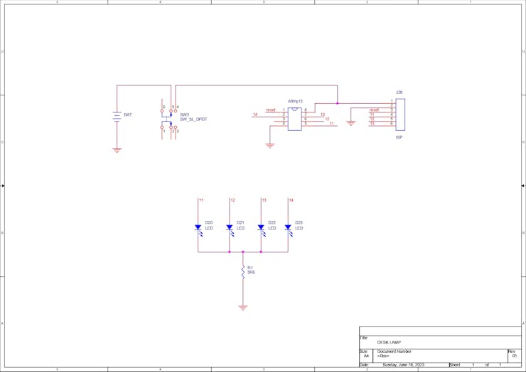

The first step is to create a schematic that includes an Attiny13A connected to four LEDs, with each LED's anode connected to the I/O pins of the Attiny13A and each LED's cathode connected to a resistance in series with GND. This load resistance is a crucial component of the circuit that will control the amount of current flowing through each LED.
A CR2032 coin cell battery is used as the power source, and between the battery's positive and the Arduino's VCC, there is an ON/OFF switch.
Also there is a CON6 Port that is linked to the Attiny13's SPI Pins and will be used in the future to flash the device with code.
After the schematic was converted into a PCB design, all of the components were then arranged inside a 50mm-diameter circular board shape.
All of our leds were placed in the center, and the other components were arranged around them.
PCBWAY


The gerber data of the PCB was exported after the PCB file was complete, and the gerber was sent to PCBWAY for samples.
An order was placed for the PCBs with yellow solder masks and white silkscreen, as they look pretty cool in general.
The PCBs were received within a week, and they were excellent, as expected.
As a leading China PCB manufacturer, PCBWAY offers one-stop PCB manufacturing services, ranging from raw material and electronic component procurement and in-house PCB fabrication to PCB assembly, testing, and shipping.
Check out PCBWAY for great PCB service at a lower cost.
PCB Assembly


- Two main parts make up the PCB assembly procedure for this project: first, we add SMD components, and then we insert THT components.
- We begin by applying solder paste to each component pad individually using a solder paste dispensing syringe.
- Next, we pick and place all the components in their proper places using ESD tweezers.
- Following the pick and place process, we place this board on a mini reflow hotplate, which heats the PCB from the bottom up to the solder paste melting temperature.
- We now add the switch in its place and solder its pads using a soldering iron.
- Next, on the bottom side, we add the CR2032 coin cell holder to its location and solder its pads from the top side of the board.
- Board assembly is complete.
Programming Attiny13A


Programming Attiny is an easy task, you just need an Arduino Nano or UNO board and a 1 uF capacitor. Here's how you can do that.
Before starting this step, you need to download and install ATTINY CORE files into the Arduino IDE, checkout the core files from here-
https://github.com/MCUdude/MicroCore
- We first open the Arduino IDE and upload the Arduino as ISP sketch to the Arduino nano board.
- We then connect the 1 uF capacitor between the GND Pin and Reset Pin of Arduino Board.
- Next we add attiny's SPI Pins (MISO, MOSI, SCK, RST) to D10, D11, D12, and D13.
- We then go to tool menu and select the board which is in this case Attiny13
- choose the right programmer (Arduino as ISP)
- then burn the bootloader, wait for few seconds and you will be greeted with a "DONE BURNING BOOTLOADER MESSAGE"
- After that, we open the sketch we want to upload, select Upload Using Programmer from the sketch menu, and our code is uploaded to the Attiny13A.
I built an Arduino as an ISP Programmer using an Arduino Mini, which I usually use to programme any AVR Device, to make things simple and easy.
You can read more about this programmer from here-
https://www.hackster.io/Arnov_Sharma_makes/multiple-attiny85-13a-programmer-84adf8
CODE
int pinsCount=4;                        // declaring the integer variable pinsCount
int pins[] = {0,1,2,3};          // declaring the array pins[]


void setup() {

  pinMode(0, OUTPUT);
  pinMode(1, OUTPUT);
  pinMode(2, OUTPUT);
  pinMode(3, OUTPUT);

}


void loop() {
  for (int i=0; i<pinsCount; i=i+1){    // chasing right
    digitalWrite(pins[i], HIGH);         // switching the LED at index i on
    delay(50);                          // stopping the program for 100 milliseconds
    digitalWrite(pins[i], LOW);          // switching the LED at index i off
  }
  for (int i=pinsCount-1; i>0; i=i-1){   // chasing left (except the outer leds)
    digitalWrite(pins[i], HIGH);         // switching the LED at index i on
    delay(50);                          // stopping the program for 100 milliseconds
    digitalWrite(pins[i], LOW);          // switching the LED at index i off
  }

}
This code sets up four LEDs connected to pins 0, 1, 2, and 3 on the Arduino board and controls them in a chasing pattern, first moving to the right and then to the left (except for the outermost LEDs). The LEDs stay on for 50 milliseconds and then turn off before moving to the next LED in the pattern.
3D Printed Circuit Holder


- We had to design a cylindrical PCB holder that lifts the PCB and keeps it inside the top glass body of the lantern in order to hold this circuit inside the body of the lantern.
- Red PLA was used with a layer height of 0.2mm and a 0.4mm nozzle to print this part, which was created in Fusion360 and exported as an STL file for 3D printing.
- To install the circuit on the 3D printed portion, we need two M2 screws.The circuit is mounted on the 3D-printed portion using two M2 screws.
RESULT


Ultimately, we assembled the lamp by only placing the glass top on top of the metal lamp frame and the PCB Holder Assembly Section.
The project is finished, and we now have a vintage oil light that employs modern tech.
Green and white LEDs were utilized in this project; red and orange LEDs would have produced a much greater flame effect, but I didn't have those at the time, so white and green LEDs were used instead.
Overall, I'm satisfied with the outcome, and my dining room now features a stunning lamp.
This is it for today folks, Please leave comments or DM me if you need any help or information regarding this project.
Special thanks to PCBWAY for supporting this project; do check them out for great PCB service at a lower cost.
Thanks again, and I will be back with a new project soon.
int pinsCount=4; // declaring the integer variable pinsCount
int pins[] = {0,1,2,3}; // declaring the array pins[]
void setup() {
pinMode(0, OUTPUT);
pinMode(1, OUTPUT);
pinMode(2, OUTPUT);
pinMode(3, OUTPUT);
}
void loop() {
for (int i=0; i<pinsCount; i=i+1){ // chasing right
digitalWrite(pins[i], HIGH); // switching the LED at index i on
delay(50); // stopping the program for 100 milliseconds
digitalWrite(pins[i], LOW); // switching the LED at index i off
}
for (int i=pinsCount-1; i>0; i=i-1){ // chasing left (except the outer leds)
digitalWrite(pins[i], HIGH); // switching the LED at index i on
delay(50); // stopping the program for 100 milliseconds
digitalWrite(pins[i], LOW); // switching the LED at index i off
}
}
Antique Lantern Project
*PCBWay community is a sharing platform. We are not responsible for any design issues and parameter issues (board thickness, surface finish, etc.) you choose.


Raspberry Pi 5 7 Inch Touch Screen IPS 1024x600 HD LCD HDMI-compatible Display for RPI 4B 3B+ OPI 5 AIDA64 PC Secondary Screen(Without Speaker)
BUY NOW


- Comments(0)
- Likes(0)
More by Arnov Arnov sharma
-
 DIY XBOX Controller
Greetings everyone, and welcome back. Here's something fun and custom.This is my version of an Xbox ...
DIY XBOX Controller
Greetings everyone, and welcome back. Here's something fun and custom.This is my version of an Xbox ...
-
 Pocket SNES
Greetings everyone, and welcome back! Today, I’ve got something fun and tiny to share—the Pocket SNE...
Pocket SNES
Greetings everyone, and welcome back! Today, I’ve got something fun and tiny to share—the Pocket SNE...
-
 Batocera Arcade Box
Greetings everyone and welcome back, Here's something. Fun and nostalgic. Right now, we are using ou...
Batocera Arcade Box
Greetings everyone and welcome back, Here's something. Fun and nostalgic. Right now, we are using ou...
-
 64x32 Matrix Panel Setup with PICO 2
Greetings everyone and welcome back.So here's something fun and useful: a Raspberry Pi Pico 2-powere...
64x32 Matrix Panel Setup with PICO 2
Greetings everyone and welcome back.So here's something fun and useful: a Raspberry Pi Pico 2-powere...
-
 Portable Air Quality Meter
Hello everyone, and welcome back! Today, I have something incredibly useful for you—a Portable Air Q...
Portable Air Quality Meter
Hello everyone, and welcome back! Today, I have something incredibly useful for you—a Portable Air Q...
-
 WALKPi PCB Version
Greetings everyone and welcome back, This is the WalkPi, a homebrew audio player that plays music fr...
WALKPi PCB Version
Greetings everyone and welcome back, This is the WalkPi, a homebrew audio player that plays music fr...
-
 Delete Button XL
Greetings everyone and welcome back, and here's something fun and useful.In essence, the Delete Butt...
Delete Button XL
Greetings everyone and welcome back, and here's something fun and useful.In essence, the Delete Butt...
-
 Arduino Retro Game Controller
Greetings everyone and welcome back. Here's something fun.The Arduino Retro Game Controller was buil...
Arduino Retro Game Controller
Greetings everyone and welcome back. Here's something fun.The Arduino Retro Game Controller was buil...
-
 Super Power Buck Converter
Greetings everyone and welcome back!Here's something powerful, The SUPER POWER BUCK CONVERTER BOARD ...
Super Power Buck Converter
Greetings everyone and welcome back!Here's something powerful, The SUPER POWER BUCK CONVERTER BOARD ...
-
 Pocket Temp Meter
Greetings and welcome back.So here's something portable and useful: the Pocket TEMP Meter project.As...
Pocket Temp Meter
Greetings and welcome back.So here's something portable and useful: the Pocket TEMP Meter project.As...
-
 Pico Powered DC Fan Driver
Hello everyone and welcome back.So here's something cool: a 5V to 12V DC motor driver based around a...
Pico Powered DC Fan Driver
Hello everyone and welcome back.So here's something cool: a 5V to 12V DC motor driver based around a...
-
 Mini Solar Light Project with a Twist
Greetings.This is the Cube Light, a Small and compact cube-shaped emergency solar light that boasts ...
Mini Solar Light Project with a Twist
Greetings.This is the Cube Light, a Small and compact cube-shaped emergency solar light that boasts ...
-
 PALPi V5 Handheld Retro Game Console
Hey, Guys what's up?So this is PALPi which is a Raspberry Pi Zero W Based Handheld Retro Game Consol...
PALPi V5 Handheld Retro Game Console
Hey, Guys what's up?So this is PALPi which is a Raspberry Pi Zero W Based Handheld Retro Game Consol...
-
 DIY Thermometer with TTGO T Display and DS18B20
Greetings.So this is the DIY Thermometer made entirely from scratch using a TTGO T display board and...
DIY Thermometer with TTGO T Display and DS18B20
Greetings.So this is the DIY Thermometer made entirely from scratch using a TTGO T display board and...
-
 Motion Trigger Circuit with and without Microcontroller
GreetingsHere's a tutorial on how to use an HC-SR505 PIR Module with and without a microcontroller t...
Motion Trigger Circuit with and without Microcontroller
GreetingsHere's a tutorial on how to use an HC-SR505 PIR Module with and without a microcontroller t...
-
 Motor Driver Board Atmega328PU and HC01
Hey, what's up folks here's something super cool and useful if you're making a basic Robot Setup, A ...
Motor Driver Board Atmega328PU and HC01
Hey, what's up folks here's something super cool and useful if you're making a basic Robot Setup, A ...
-
 Power Block
Hey Everyone what's up!So this is Power block, a DIY UPS that can be used to power a bunch of 5V Ope...
Power Block
Hey Everyone what's up!So this is Power block, a DIY UPS that can be used to power a bunch of 5V Ope...
-
 Goku PCB Badge V2
Hey everyone what's up!So here's something SUPER cool, A PCB Board themed after Goku from Dragon Bal...
Goku PCB Badge V2
Hey everyone what's up!So here's something SUPER cool, A PCB Board themed after Goku from Dragon Bal...
-
Programmable Mist Maker - XIAO / QT PY Extension
172 0 0 -
RadioHAT - Raspberry Pi radio development platform
182 0 1 -
-
-
-
-
ARPS-2 – Arduino-Compatible Robot Project Shield for Arduino UNO
2767 0 5 -
A Compact Charging Breakout Board For Waveshare ESP32-C3
3275 3 8 -
AI-driven LoRa & LLM-enabled Kiosk & Food Delivery System
3529 2 2


