A Modular Multilevel Inverter with Transformer-Based Submodule Voltage Balancing
Overview
The inverter converts a 400V DC to an 8 level single-phase AC-signal.
It has a rated power of 3.33 kW and is a scaled down version targeting automotive drivetrains.
Inputs:
- DC-voltage for inverting
- Auxiliary power
- Optical signals to determine the switching state
Outputs:
- AC-voltage
- Measured voltage and current
Basic idea
Multi-level inverter provide many advantages such as low power components and higher output signal resolution.
However, this also comes at a drawback of complicated control and bulky DC-link capacitors which are needed to ensure that the output voltage levels stay balanced.
This project overcomes this issue by using magnetic fields to balance the voltage levels through a multi-active bridge. To ease the control and allow scaling up to many voltage levels, the multi-active bridge is using a specifically designed auxiliary power supply.
The inverter is an assembly consisting of three parts:
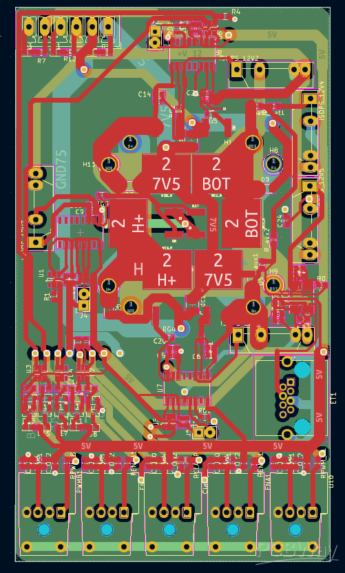
- The auxiliary supply board
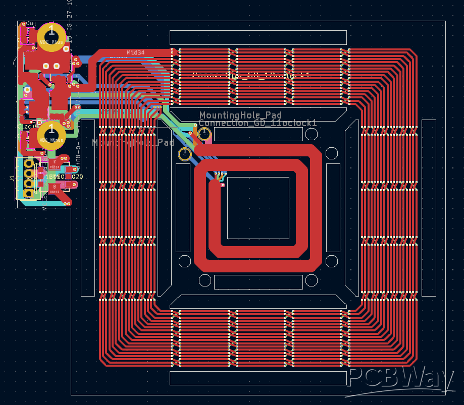
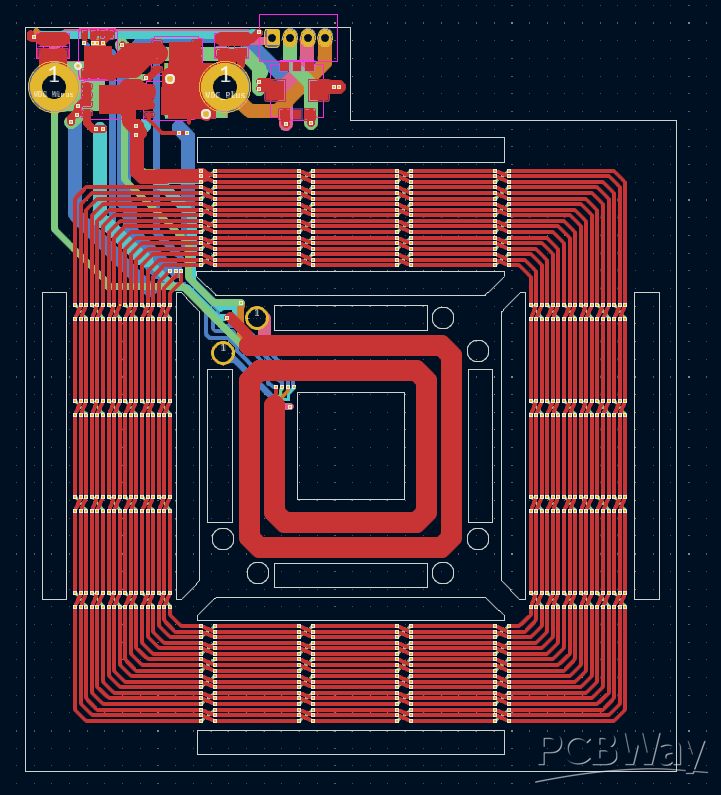
- A multi-active bridge consisting of two mirrored boards, each of which has two transformer windings, one for the supply of the switches and one for power transfer
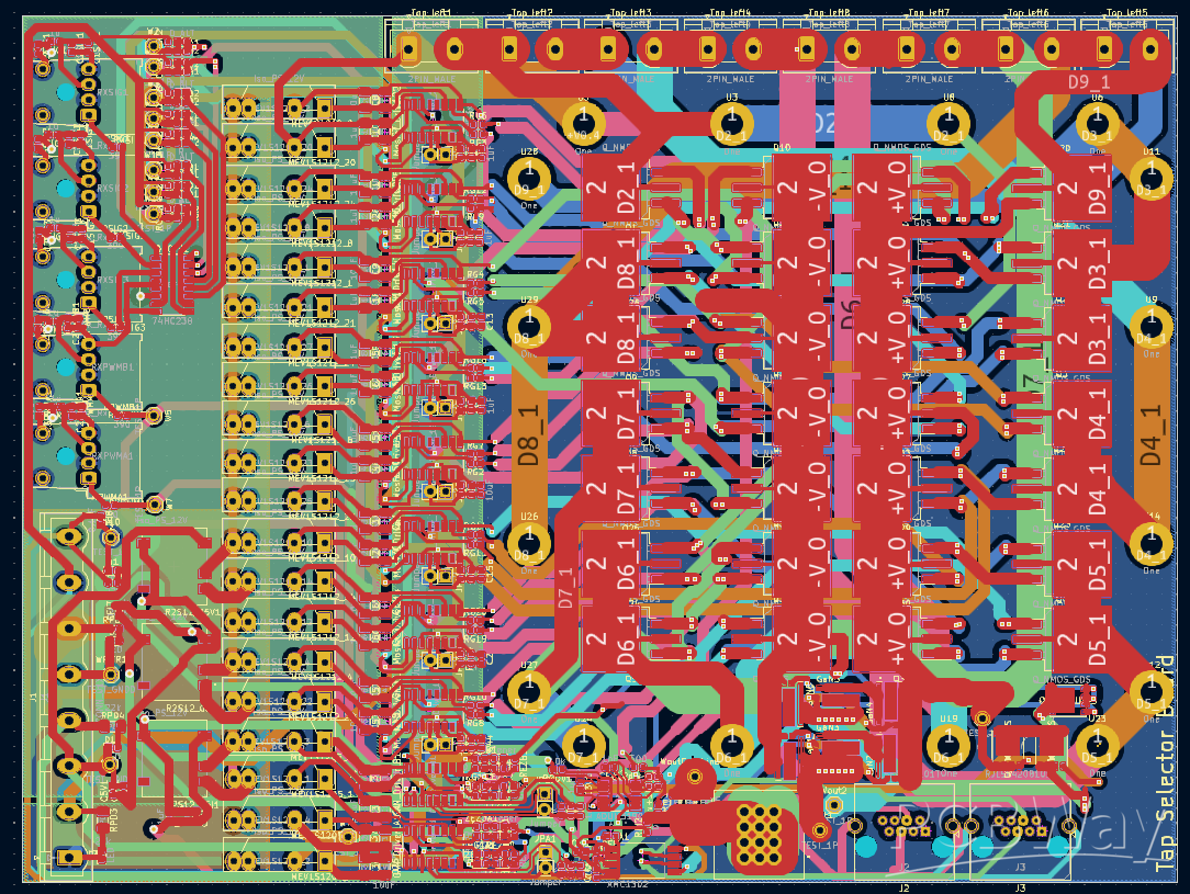
- An inverter which has a simplified structure assuming that it always stays balanced. The structure is a special case of a P2 multilevel inverter omitting all redundant states
A special 3D-assembly is necessary to make the inverter operating.
This inverter with integrated balancer was part of my PhD.
A detailed description can be found in Chapter 6 here:
The other chapters give an overview over the system model, modulation, ...
https://discovery.ucl.ac.uk/id/eprint/10178459/
Please write me a PM if you are interested in the full BOM.


A Modular Multilevel Inverter with Transformer-Based Submodule Voltage Balancing
*PCBWay community is a shared platform and we are not responsible for any design issues.
- Comments(6)
- Likes(15)
-
 Engineer
Jan 21,2024
-
 Engineer
Jan 20,2024
-
 Engineer
Jan 20,2024
-
 Engineer
Jan 20,2024
-
 Engineer
Jan 16,2024
-
 Engineer
Jan 16,2024
-
 Engineer
Jan 16,2024
-
 Engineer
Jan 16,2024
-
 Engineer
Jan 16,2024
-
 Engineer
Jan 16,2024
-
 Engineer
Jan 16,2024
-
 Engineer
Jan 16,2024
-
 Engineer
Jan 16,2024
-
 Engineer
Jan 16,2024
-
 Engineer
Jan 16,2024
- 16 USER VOTES
- YOUR VOTE 0.00 0.00
- 1
- 2
- 3
- 4
- 5
- 6
- 7
- 8
- 9
- 10
- 1
- 2
- 3
- 4
- 5
- 6
- 7
- 8
- 9
- 10
- 1
- 2
- 3
- 4
- 5
- 6
- 7
- 8
- 9
- 10
- 1
- 2
- 3
- 4
- 5
- 6
- 7
- 8
- 9
- 10

-
8design
-
6usability
-
7creativity
-
5content

-
9design
-
5usability
-
9creativity
-
5content
-
10design
-
10usability
-
10creativity
-
10content
-
10design
-
10usability
-
10creativity
-
10content
-
10design
-
10usability
-
10creativity
-
10content
-
10design
-
10usability
-
10creativity
-
10content
-
10design
-
10usability
-
10creativity
-
10content
-
10design
-
10usability
-
10creativity
-
10content
-
10design
-
10usability
-
10creativity
-
10content
-
10design
-
10usability
-
10creativity
-
10content
-
10design
-
10usability
-
10creativity
-
10content
-
10design
-
10usability
-
10creativity
-
10content
-
10design
-
10usability
-
10creativity
-
10content
-
10design
-
10usability
-
10creativity
-
10content
-
10design
-
10usability
-
10creativity
-
10content
-
10design
-
10usability
-
10creativity
-
10content
 More by Ferdinand Grimm
-
Open Source Very Large Stick - Freejoy & MMjoy2 breakout board
503 0 0 -
RF Control training board for students based on ESP32 C3
676 0 2 -
Aquarius+ Computer, Standard PCB
897 0 4 -
KINETIC COASTERS with a TWIST! Laser or 3D Print some DIY Magic
605 0 1 -
RPI - 8 IO PLC With ATTiny85 Watch Dog
531 0 1 -
Nintendo Famicom HVC-001 Controller Shells
626 0 1 -
COMMODORE 128 DIAGNOSTIC REV.785260 KEYBOARD DONGLE
596 0 4 -
COMMODORE 128 15KHz DISPLAY ADAPTER (C128 80 COLUMN ADAPTER)
800 1 6 -


