


|
arduino IDEArduino
|
|

|
Esp Home Home Assistant AddonEsp Home
|
|

|
Home Assistant OS |
|
|
|
MCU-8266-12E IoT ControllerMakerIoT2020
|
Custom ATMEGA328P PCB with Build-in 8Ch Bi-Directional Logic Level Converter
What is this:
In August 2021, MakerIoT2020 released the design files of our MCU-8266-12E IoT Controller PCB. Upon completion of this project,
we realised that the controller in its current state is actually quite limited. (Having only 2 relay outputs, and an additional 6 inputs/outputs - wired to be used mainly for pushbuttons or LED indicators...)
I2C and SPI ports, as well as additional IO lines from the ESP8266-12E, are available, but things could get messy if we added breakout modules with wires to these ports. It will however still stay limited to the amount of IO ports available on the single ESP8266 chip...
An Add-on Shield or Card seemed like a better solution, and in fact, we designed one right away. It could however not be tested right away, and we did not want to produce a PCB of an untested design.
At the same time, while playing around with the APE ( Arduino Port Extender ) protocol that is available for ESPHome, we thought that, since it would be quite easy to modify the existing sketch, and rewrite the C header file that defines the APE custom component, It would actually be a great idea to put an ATMEGA328P onto the add-on card. That way, It would be possible to add quite a lot of additional IO Lines, with some Analogs Inputs as well. It still does not take care of the Relay outputs, but that shall be addressed later...
Another point to consider was the fact that the ATMEGA328P would be running from 5v ( I wanted it to operate at 16Mhz, where it seems that only 8Mhz is possible when running at 3.3v? ). The ESP runs at 3.3v however, so all signals exchanged between the two microcontrollers will need to pass through a level converter.
I decided to add an onboard level converter, and while I was at that, gave it 8 channels so that I could use more than one serial protocol if needed ( SPI as well as I2C ). I also decided that since I was designing anyway, I would address some of the issues that I have with the existing Arduino Nano board, adding a dedicated 3.3v LDO Voltage Regulator, additional power outputs, and a jumper to select the source for the 3.3v input --- In other words, I might have totally overengineered the board :) a common problem in my life :)
I also wanted to experiment with uploading ATMEGA chips through the ISCP interface, something that I have not done in quite a while, since I moved away from PIC microcontrollers, and started using Arduino and ESP32/ESP8266 type chips...
The Circuit Diagram
The board is for all purposes a standard Arduino Nano, with some minor modifications as we shall see below.

The main modification to the standard Arduino Nano circuit is the addition of a second LDO voltage regulator, for providing 3.3v
with a jumper to select the input of this LDO Regulator to be either directly from VIN, or from the 5v line. ( Maybe not the best of practices.. )
LED indicators for the status of both 5v and 3.3v power lines were also added. The AREF line was not broken out to a header, as I very seldom use that anyway. Apart from that, the GPIO breakout to the headers follows the standard Arduino Nano layout.

The 8Ch Logic level converter is based on the BSS138 N-Channel Mosfet, used in many Logic Level converter breakout boards currently available. In the current version of this PCB, the converter is fixed to 5v on the HV side and 3.3v on the LV side. Later versions may have the option to provide custom voltages to the converters, making it a bit more flexible in use.
Additional 3.3v, 5v and Ground headers were also added to the PCB.

USB Serial was not initially part of my plan, but after some thinking on the matter, I decided that it would actually be a good idea to add it. This would enable me to use this PCB as a standalone "Arduino compatible" device as well...
Rendered PCB Images

Front Side

Back Side

3D Render

RAW Layout Design
Assembly and testing
The PCB was assembled and reflowed by myself, using a hotplate.

Upon completion, a small bit of reworking was needed, as well as assembly of the headers and other through-hole components.
Initial flashing of the Arduino Nano bootloader went very well, with none of the reported issues as stated by many people online.
Subsequent uploading of code through the USB-to-serial converter also worked as expected.
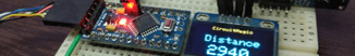
The Logic Level converters perform quite well too. Below is a short video of a test using an ST7789 TFT Display ( SPI ), and an SSD1306 OLED Display ( I2C ) using libraries from Adafruit. The code was uploaded via ISCP using the Cytron Maker Uno and the Arduino IDE ( using Arduino as ISP )
Conclusion
This project started out as an idea to do something, and then grew into something completely different. Although I did end up testing it with the APE and ESPHome, I believe that it is quite capable to stand on its own and being used as a standalone development and prototyping board (In my own view at least). Everything works as expected, and the built-in level converters really goes a long way towards reducing the clutter associated with a breadboard.
PCBWay also did their usual great work at manufacturing the board exactly as designed. Thank you, the quality is excellent, as usual :)
/*
Ports:
  0 0 .. 13 13
  A0: 14, A1: 15, A2: 16, A3: 17: A4: 18: A5: 19: A6: 20, A7: 21
  port bits: 5 ... 0..32
  0:   0: 00000
  1:   1: 00001
  A7: 21: 10101
*/

#include <Arduino.h>
#include <Wire.h>

//#define DEBUG // remove debug so pin 0 and 1 can be used for IO

#define I2C_ADDRESS 8

void onRequest();
void onReceive(int);

void setup()
{
#ifdef DEBUG
  Serial.begin(115200);
  Serial.println(F("Init "));
#endif

  analogReference(INTERNAL);

  Wire.begin(I2C_ADDRESS);
  Wire.onRequest(onRequest);
  Wire.onReceive(onReceive);

#ifdef DEBUG
  Serial.println(F("Wire ok"));
#endif
}

void loop()
{
  //int temp = analogRead(A1);
  //Serial.println(temp);
}

volatile byte buffer[3];
volatile byte len = 1;

#define DIGITAL_READ(b, pin, mask) \
  if (digitalRead(pin))            \
    buffer[b] |= mask;

void readDigital()
{
  len = 3;
  buffer[0] = 0;
  DIGITAL_READ(0, 0, 1);
  DIGITAL_READ(0, 1, 2);
  DIGITAL_READ(0, 2, 4);
  DIGITAL_READ(0, 3, 8);
  DIGITAL_READ(0, 4, 16);
  DIGITAL_READ(0, 5, 32);
  DIGITAL_READ(0, 6, 64);
  DIGITAL_READ(0, 7, 128);

  buffer[1] = 0;
  DIGITAL_READ(1, 8, 1);
  DIGITAL_READ(1, 9, 2);
  DIGITAL_READ(1, 10, 4);
  DIGITAL_READ(1, 11, 8);
  DIGITAL_READ(1, 12, 16);
  DIGITAL_READ(1, 13, 32);
  DIGITAL_READ(1, A0, 64);
  DIGITAL_READ(1, A1, 128);

  buffer[2] = 0;
  DIGITAL_READ(2, A2, 1);
  DIGITAL_READ(2, A3, 2);

// I2C
//DIGITAL_READ(2, A4, 4);
//DIGITAL_READ(2, A5, 8);

// DIGITAL READ not supports on A3 .. A7
#ifdef DEBUG_READ
  Serial.print(F("Read 3 bytes: "));
  Serial.print(buffer[0]);
  Serial.print(' ');
  Serial.print(buffer[1]);
  Serial.print(' ');
  Serial.println(buffer[2]);

#endif
}
void readAnalog(int pin)
{
  int val = analogRead(A0 + pin);
  len = 2;
  buffer[0] = val & 0xFF;
  buffer[1] = (val >> 8) & 0b11;
#ifdef DEBUG_READ
  Serial.print(F("Read analog pin "));
  Serial.println(pin);
#endif
}

void onRequest()
{
  Wire.write(const_cast<uint8_t *>(buffer), len);
}

#define CMD_DIGITAL_READ 0x0

#define CMD_WRITE_ANALOG 0x2
#define CMD_WRITE_DIGITAL_HIGH 0x3
#define CMD_WRITE_DIGITAL_LOW 0x4

#define CMD_SETUP_PIN_OUTPUT 0x5
#define CMD_SETUP_PIN_INPUT_PULLUP 0x6
#define CMD_SETUP_PIN_INPUT 0x7

// 8 analog registers.. A0 to A7
// A4 and A5 not supported due to I2C
#define CMD_ANALOG_READ_A0 0b1000 // 0x8
// ....
#define CMD_ANALOG_READ_A7 0b1111 // 0xF

#define CMD_SETUP_ANALOG_INTERNAL 0x10
#define CMD_SETUP_ANALOG_DEFAULT 0x11

void onReceive(int numBytes)
{
#ifdef DEBUG_READ
  Serial.print("Received bytes: ");
  Serial.println(numBytes);
#endif
  int cmd = Wire.read();

  switch (cmd)
  {
  case CMD_DIGITAL_READ:
    readDigital();
    break;
  }

  if (cmd >= CMD_ANALOG_READ_A0 && cmd <= CMD_ANALOG_READ_A7)
  {
    readAnalog(cmd & 0b111);
    return;
  }

  int pin = Wire.read();

  switch (cmd)
  {
  case CMD_WRITE_DIGITAL_HIGH:
  case CMD_WRITE_DIGITAL_LOW:
  {
    bool output = cmd == CMD_WRITE_DIGITAL_HIGH;
    digitalWrite(pin, output);
#ifdef DEBUG
    Serial.print(F("Pin "));
    Serial.print(pin);
    Serial.println(output ? F(" HIGH") : F(" LOW"));
#endif
    break;
  }
  case CMD_WRITE_ANALOG:
  {
    int val = Wire.read() & (Wire.read() << 8);
    analogWrite(pin, val);
#ifdef DEBUG
    Serial.print(F("Pin "));
    Serial.print(pin);
    Serial.print(F(" Analog write "));
    Serial.println(val);
#endif
    break;
  }
  case CMD_SETUP_PIN_OUTPUT:
    pinMode(pin, OUTPUT);
#ifdef DEBUG
    Serial.print(F("Pin "));
    Serial.print(pin);
    Serial.println(F(" OUTPUT"));
#endif
    break;
  case CMD_SETUP_PIN_INPUT:
    pinMode(pin, INPUT);
#ifdef DEBUG
    Serial.print(F("Pin "));
    Serial.print(pin);
    Serial.println(F("INPUT"));
#endif
    break;
  case CMD_SETUP_PIN_INPUT_PULLUP:
    pinMode(pin, INPUT_PULLUP);
#ifdef DEBUG
    Serial.print(F("Pin "));
    Serial.print(pin);
    Serial.println(F("INPUT PULLUP"));
#endif
    break;
  case CMD_SETUP_ANALOG_INTERNAL:
    analogReference(INTERNAL);
#ifdef DEBUG
    Serial.println(F("Analog reference INTERNAL"));
#endif
    break;
  case CMD_SETUP_ANALOG_DEFAULT:
    analogReference(DEFAULT);
#ifdef DEBUG
    Serial.println(F("Analog reference DEFAULT"));
#endif
    break;
  }
}


Custom ATMEGA328P PCB with Build-in 8Ch Bi-Directional Logic Level Converter
*PCBWay community is a shared platform and we are not responsible for any design issues.


- Comments(0)
- Likes(3)
- 1 USER VOTES
- YOUR VOTE 0.00 0.00

-
7design
-
10usability
-
10creativity
-
10content
More by Jean Redelinghuys MakerIoT2020
-
 PCB_MCP23008_2023-10-08
MCP23008 BreakoutI designed this breakout to assist me during prototyping my next version of the “RP...
PCB_MCP23008_2023-10-08
MCP23008 BreakoutI designed this breakout to assist me during prototyping my next version of the “RP...
-
 PCB_XiaoRP2040-Mouse-REV2
Xiao RP2040 Joystick Mouse – revision 2.00Revision 1.0 of the ProjectOver the last few months, I hav...
PCB_XiaoRP2040-Mouse-REV2
Xiao RP2040 Joystick Mouse – revision 2.00Revision 1.0 of the ProjectOver the last few months, I hav...
-
 Multi Purpose IO Card
Multi-Purpose IO CardWhen we are working on a prototype, we always need access to pushbuttons, encod...
Multi Purpose IO Card
Multi-Purpose IO CardWhen we are working on a prototype, we always need access to pushbuttons, encod...
-
 Variable Voltage Power Module
Powering electronics projects are always challenging. This Variable vol...
Variable Voltage Power Module
Variable Voltage Power ModulePowering electronics projects are always challenging. This Variable vol...
-
 I2C Matrix Keypad
An I2C Matrix KeypadThe completed I2C Matrix KeypadIn a previous post this month I introduced my 4×4...
I2C Matrix Keypad
An I2C Matrix KeypadThe completed I2C Matrix KeypadIn a previous post this month I introduced my 4×4...
-
 ESP32-S Development Board, in "Arduino Uno" form factor
UPDATE 24/06/2023:This board now has a Hardware Revision 2.0 available. It is the same board but wit...
ESP32-S Development Board, in "Arduino Uno" form factor
UPDATE 24/06/2023:This board now has a Hardware Revision 2.0 available. It is the same board but wit...
-
 W307186ASC94_Gerber_PCB_USB-Ports
USB Power Supply ModuleUSB Ports are quite handy to power all our day-to-day electronic devices, but...
W307186ASC94_Gerber_PCB_USB-Ports
USB Power Supply ModuleUSB Ports are quite handy to power all our day-to-day electronic devices, but...
-
 Atmega 328P based PWM controller Card
ATMega 328P Based PWM controller CardAs part of my recent ESP-12E I2C Base Board project, I designed...
Atmega 328P based PWM controller Card
ATMega 328P Based PWM controller CardAs part of my recent ESP-12E I2C Base Board project, I designed...
-
 W307186ASC71_Gerber_PCB_ESP-Now Remote
Today we will look at the remote control unit for the Robotic Toy Car – Part 6.The project is close ...
W307186ASC71_Gerber_PCB_ESP-Now Remote
Today we will look at the remote control unit for the Robotic Toy Car – Part 6.The project is close ...
-
 W307186ASV69_Gerber_PCB_Robot-Car-MCU-Board Prototype
In our last project, we started working on repurposing an old toy car. In this part, Robot Toy Car –...
W307186ASV69_Gerber_PCB_Robot-Car-MCU-Board Prototype
In our last project, we started working on repurposing an old toy car. In this part, Robot Toy Car –...
-
 W307186ASV62_Gerber_PCB_DUAL-H-Bridge
by makeriot2020 on May 27, 2022Many of us have old toys laying around the house, they belong to ou...
W307186ASV62_Gerber_PCB_DUAL-H-Bridge
by makeriot2020 on May 27, 2022Many of us have old toys laying around the house, they belong to ou...
-
 CAN-BUS Breakout
Breadboard Compatible CAN-BUS Breakout ModuleWhat is this:Some of us have already used the commonly ...
CAN-BUS Breakout
Breadboard Compatible CAN-BUS Breakout ModuleWhat is this:Some of us have already used the commonly ...
-
 RA-02 Breakout with Level converters
Breadboard and beginner-friendly RA-02 Breakout ModuleMost Makers and electronics enthusiasts may al...
RA-02 Breakout with Level converters
Breadboard and beginner-friendly RA-02 Breakout ModuleMost Makers and electronics enthusiasts may al...
-
 ATMEGA328P Module with integrated LoRa and CAN Bus
ATMEGA328P Module with integrated LoRa and CAN-BUSINTRODUCTIONIn my quest to perfect my LoRa telemet...
ATMEGA328P Module with integrated LoRa and CAN Bus
ATMEGA328P Module with integrated LoRa and CAN-BUSINTRODUCTIONIn my quest to perfect my LoRa telemet...
-
 Sx127x-Ra-02-Test-Module with ATMEGA328P-AU
SX127x LoRa/FSK/OOK Prototype Radio BoardI recently had a requirement to do some automation/telemetr...
Sx127x-Ra-02-Test-Module with ATMEGA328P-AU
SX127x LoRa/FSK/OOK Prototype Radio BoardI recently had a requirement to do some automation/telemetr...
-
 USB-ASP Programmer ATMEGA8
Build your own USB-ASP Programmer CloneBymakeriot2020 FEB 21, 2022 Arduino, ASP programmerUsing mor...
USB-ASP Programmer ATMEGA8
Build your own USB-ASP Programmer CloneBymakeriot2020 FEB 21, 2022 Arduino, ASP programmerUsing mor...
-
 Gerber_PCB_Soil-Moisture-project-M5
A Simple IoT Plant Watering SolutionThis is a Simple IoT Plant Watering Solution, done as another co...
Gerber_PCB_Soil-Moisture-project-M5
A Simple IoT Plant Watering SolutionThis is a Simple IoT Plant Watering Solution, done as another co...
-
 Gerber_PCB_PCB_CPU789_2_2024-01-05 (1)_2024-01-10
A Student designed ESP8266 Dev BoardThis is a student-designed ESP8266 Dev board. This project came ...
Gerber_PCB_PCB_CPU789_2_2024-01-05 (1)_2024-01-10
A Student designed ESP8266 Dev BoardThis is a student-designed ESP8266 Dev board. This project came ...
-
Open Source Very Large Stick - Freejoy & MMjoy2 breakout board
291 0 0 -
RF Control training board for students based on ESP32 C3
400 0 2 -
-
KINETIC COASTERS with a TWIST! Laser or 3D Print some DIY Magic
440 0 1 -
RPI - 8 IO PLC With ATTiny85 Watch Dog
385 0 0 -
Nintendo Famicom HVC-001 Controller Shells
489 0 1 -
COMMODORE 128 DIAGNOSTIC REV.785260 KEYBOARD DONGLE
474 0 4 -
COMMODORE 128 15KHz DISPLAY ADAPTER (C128 80 COLUMN ADAPTER)
573 1 4 -


