Threaded holes are widely used in CNC machined parts for fastening, assembly, and maintenance. From simple mounting holes to precision mechanical connections, properly designed threads help ensure reliable assembly and long-term performance.
However, designing a threaded hole involves more than selecting a screw size. Thread type, tap drill diameter, hole depth, material, and machining method all affect the final result. This guide covers common thread types, machining methods, and essential CNC thread design guidelines to help you create parts that are easier to manufacture, inspect, and assemble.
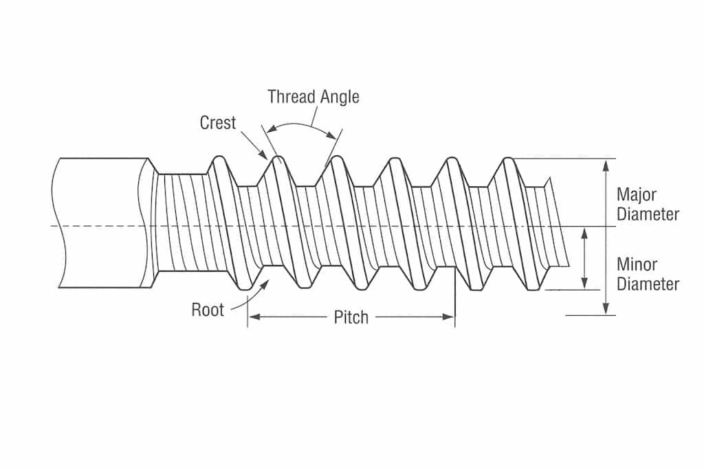
(Thread Nomenclature)
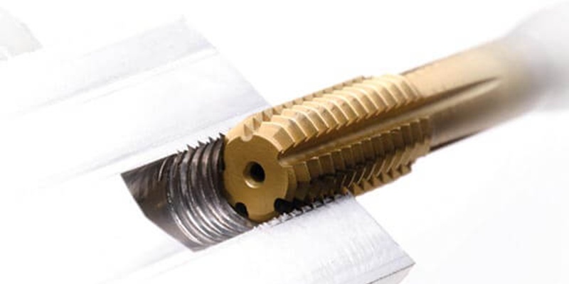
A threaded hole is a hole with internal helical grooves designed to engage with an external thread, such as a bolt or screw. In CNC machining, internal threads are commonly produced through tapping or thread milling.
Threaded holes allow components to be fastened without requiring a separate nut on the opposite side. They are widely used in machine housings, brackets, fixtures, enclosures, and precision mechanical components.
Depending on the part geometry and assembly requirements, threaded holes can be classified into two main types.
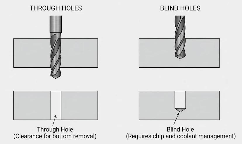
(Blind Holes vs. Through Holes)
Through holes extend completely through the workpiece. They generally provide better chip evacuation and allow greater flexibility for tapping tools. However, the exit side may require deburring, and the entire hole length does not automatically need to be threaded.
Blind holes terminate within the material and are commonly used when the opposite surface must remain intact or when a screw is installed from only one side.
Blind threaded holes require more careful depth planning because the tapping tool needs additional space at the bottom of the hole. The drilled depth must account for the drill point, incomplete threads, and tool clearance.
The choice between blind and through holes depends on the component geometry, available space, fastening requirements, and manufacturing method.
Different thread profiles and standards serve different applications. Selecting the right thread type ensures compatibility with fasteners and avoids unnecessary machining complexity.
ISO Metric Threads (M) and Unified Threads (UNC/UNF) are widely used for mechanical fastening.
Metric threads use a 60° thread profile and are specified by nominal diameter and pitch, such as M6 × 1.0. Unified threads are commonly used in North American applications and are specified by nominal diameter, threads per inch (TPI), and thread series.
Metric and Unified threads should not be treated as interchangeable simply because their nominal diameters are similar. Always follow the thread standard specified by the mating component or engineering drawing.
Pipe threads, such as NPT, NPTF, and BSP series, are used in fluid, gas, and piping connections. Their sealing requirements depend on the thread form, taper, and sealing method.
Power transmission threads, including trapezoidal, square, and buttress threads, are designed for applications involving motion transmission or substantial axial loads.
For general CNC machined parts, standard metric or Unified threads are usually sufficient. Specialized thread profiles should be specified when the application requires them.
Coarse threads have a larger pitch, while fine threads have a smaller pitch for the same nominal diameter.
Coarse threads are commonly used for general fastening because they are practical for routine assembly and relatively tolerant of handling and minor contamination.
Fine threads provide finer axial adjustment and, for comparable nominal diameters, may offer a larger tensile stress area. However, they require appropriate machining and inspection and can be more sensitive to thread damage.
The choice depends on material, loading conditions, available engagement length, and the mating fastener. Thread pitch alone does not determine joint strength or resistance to loosening.
For detailed thread profiles, standards, and specifications, refer to our CNC Thread Standards and Types Guide.
Before cutting an internal thread, a hole must be drilled to the appropriate diameter. This is known as the tap drill hole.
The tap drill diameter is smaller than the nominal thread diameter, leaving enough material to form the internal thread profile.
If the hole is too large, the resulting thread may have insufficient engagement. If it is too small, tapping forces increase, potentially causing poor thread quality or tool breakage.
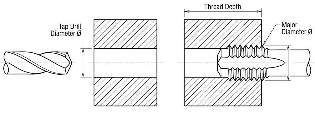
For standard ISO metric threads, a commonly used preliminary estimate for cutting taps is:
Tap drill diameter ≈ Major diameter − Pitch
For example, an M6 × 1.0 thread has a nominal diameter of 6 mm and a pitch of 1.0 mm.
6 − 1.0 = 5.0 mm.
A 5.0 mm drill is therefore a common starting point for an M6 × 1.0 internal thread.
This formula is a practical estimate, not a substitute for standard tap drill tables. The appropriate hole diameter depends on the thread standard, required thread engagement, material, tolerance, and tapping method.
Form taps also require different hole preparation because they displace material rather than remove it.
For actual machining, always refer to the recommended tap drill size for the specified thread and material.
See our CNC Thread Tap Drill Size Chart for detailed metric, Unified, and pipe thread dimensions.
Before tapping, the hole entrance is often chamfered to remove burrs and provide a smoother entry for the tap or fastener.
A suitable chamfer can help guide the tool into the hole and improve fastener assembly. However, an excessively large chamfer reduces the available full thread length near the entrance.
For CNC machined parts, the chamfer should be appropriate for the thread size, fastener geometry, and assembly requirements. If the entrance geometry is critical, specify it in the engineering drawing.
CNC threaded holes are commonly produced through drilling followed by tapping or thread milling. The appropriate method depends on thread size, material, hole geometry, production quantity, and required accuracy.
The first step is to drill a hole to the recommended tap drill diameter.
The hole must be large enough for the selected threading method while leaving sufficient material to form the required thread profile.
For blind holes, the drilled depth must exceed the required effective thread depth to accommodate the drill point, incomplete threads, and necessary tool clearance.
Tapping uses a cutting or forming tool to produce internal threads in a prepared hole.
Common cutting tap types include:
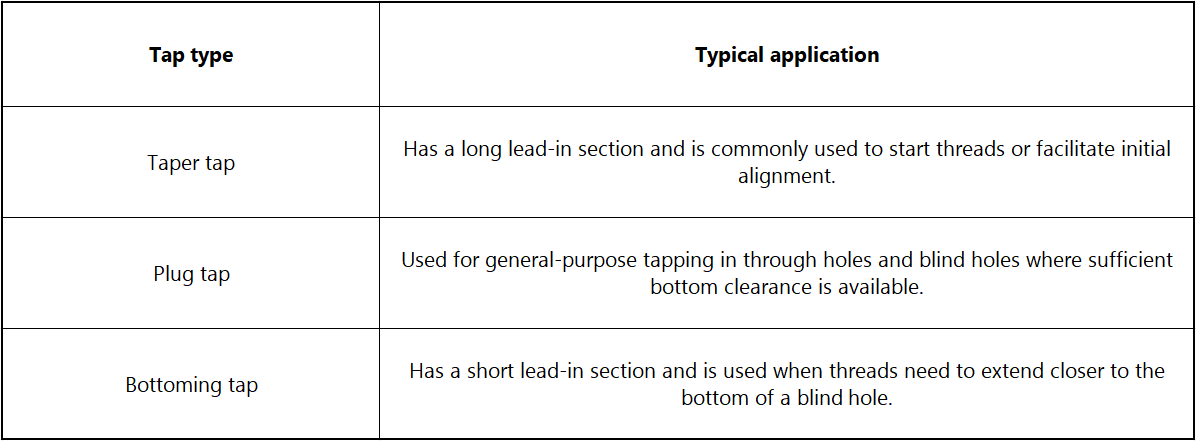
These taps differ mainly in their lead geometry and ability to form threads near the bottom of a hole. A bottoming tap does not eliminate the need for clearance at the bottom of a blind hole.
Actual tool suitability depends on the tap design, thread size, material, and machining conditions.
Cutting taps remove material to form the thread profile. Forming taps displace material without producing conventional cutting chips and are suitable for certain ductile materials when the hole diameter and material conditions are appropriate.
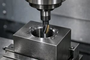
(thread milling internal hole)
Thread milling uses a rotating milling cutter to generate the thread profile through a controlled toolpath.
Compared with conventional tapping, thread milling can provide greater flexibility for different thread diameters and may offer better control over thread dimensions through toolpath adjustments.
It can also be useful for certain large-diameter, deep, or specialized threads. In suitable machining setups, it can reduce the risk of a broken tap becoming trapped in a workpiece.
However, thread milling may require more programming and machining time, particularly for simple standard threads in high-volume production.
The final method should be selected according to the part geometry, material, thread specifications, and production requirements.
Good CNC thread design considers tool access, material strength, hole geometry, and the intended assembly. The following guidelines help reduce machining difficulty and improve the reliability of threaded components.
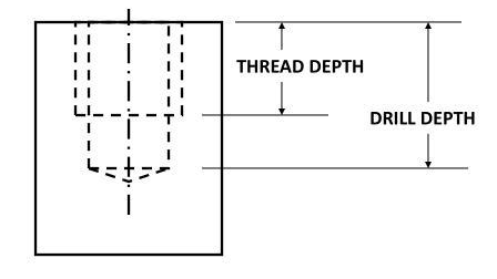
(thread depth vs drill depth)
Thread engagement length is the actual length over which the internal and external threads engage. It is different from the total drilled depth.
For blind holes, distinguish between effective thread depth and total drill depth. The drilled depth should allow for the drill point, incomplete threads, and necessary tool clearance.
A thread engagement length of approximately 1 to 1.5 times the nominal diameter is sometimes used as an initial guideline for metal fastening applications. For an M6 thread, this corresponds to approximately 6–9 mm of engagement.
However, this is not a universal strength requirement. The required length depends on the workpiece material, fastener strength, loading conditions, and the risk of internal thread stripping.
Softer materials, high loads, and repeated assembly may require a different design. Where joint strength is critical, calculate the required engagement rather than relying solely on a diameter ratio.
Threaded holes should be positioned where drilling and tapping tools can approach the surface properly.
Holes located on angled or curved surfaces may require a suitable flat or machined seating surface to ensure consistent tool entry and proper fastener seating.
Also, avoid placing threaded holes too close to part edges, thin walls, or adjacent features. Insufficient surrounding material can weaken the component and make machining more difficult.
The required edge distance and wall thickness depend on the thread diameter, material, loading conditions, and part geometry. There is no single minimum distance suitable for every application.
Different materials have different machining characteristics and thread strength.
Aluminum alloys are generally machinable, but internal threads may be more susceptible to stripping under high loads or repeated assembly. For plastic components or parts requiring frequent disassembly, threaded inserts may provide a more durable fastening interface.
Surface treatments also require attention. Anodizing, powder coating, and other coatings can affect thread fit and clearance.
Where necessary, specify whether threaded holes should be masked during finishing or receive post-processing. For critical threaded features, consider the effect of the coating thickness on the required fit and inspection.
CNC machining and 3D printing can both produce threaded features, but their design considerations differ.
CNC machined metal threads are commonly produced through tapping or thread milling and can be specified according to established thread standards.
In 3D printing, thread quality depends more heavily on printing technology, material, layer orientation, and feature resolution. Threaded inserts may be useful for plastic parts that require repeated assembly.
When designing parts that combine CNC machined and 3D printed components, consider thread compatibility, tolerances, material behavior, and assembly loads.
For more information on printed threads, inserts, and mechanical joints, see our guide to Designing Threads, Inserts & Joints for 3D Printing.
Successful CNC thread design starts with selecting the appropriate thread standard, specifying the correct tap drill size, and allowing sufficient space for machining and fastener engagement. Clear engineering drawings and practical design decisions can help reduce machining risks, improve assembly reliability, and avoid unnecessary manufacturing costs.
PCBWay provides CNC machining services for prototypes and production parts. From material selection and machining to DFM review, our team can help manufacture threaded components according to your design requirements.