When working on schematic design, engineers often encounter situations like this: to meet the core functional requirements, a 100-pin MCU is selected, but only 60 pins are actually used. Or a 4-channel op-amp is selected, but only three channels are needed. Some ICs may also have pins marked as NC. Seeing all those pins labeled as "Not Connected" on the schematic can be confusing.
Should these unused pins simply be left floating? Should they be connected to ground? Or should they be connected to a power supply? Improper handling of unused pins can lead to undefined input states, increased power consumption, or noise interference, and in severe cases may even affect device reliability. This article explains how to properly handle these seemingly minor but important details in schematic design.
Many ICs today use CMOS technology. One key rule to remember is: do not leave CMOS inputs floating, especially digital input pins.
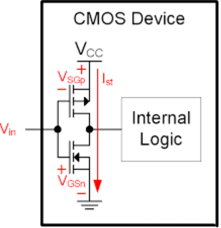
(CMOS device)
This can be understood from the internal structure of CMOS circuits. A typical CMOS input stage consists of an inverter made up of a PMOS and an NMOS connected in series.
When the input is low, the PMOS is on and the NMOS is off. When the input is high, the PMOS is off and the NMOS is on. Under ideal static conditions, only a very small leakage current flows, giving CMOS circuits very low static power consumption.
What happens when an input is left floating? Because the input has very high impedance, it can easily be affected by surrounding electromagnetic noise, parasitic coupling, and leakage current. As a result, the input voltage may become undefined and fluctuate between low and high levels.
When the input voltage falls within the transition region of the CMOS input stage, the PMOS and NMOS may both be partially turned on, causing increased supply current.
In other words, floating CMOS pins have no guaranteed logic state, so it is impossible to reliably determine whether the input will be interpreted as a high or low level.
Modern MCUs usually provide multifunctional GPIOs. For unused GPIOs, follow the requirements in the device datasheet and configure the corresponding IO as an output with a defined state, such as driving it low or high. If supported by the device, it can also be configured as an input with an internal pull-up or pull-down.
When permitted by the device, this eliminates the need for external pull-up or pull-down resistors, saving components and PCB space.
For critical pins such as interrupt, reset, and mode-selection pins, however, their default logic states should be clearly defined. Whether an external pull-up or pull-down resistor is required should be determined according to the datasheet and reference design to prevent unintended triggering.
Op-amps and ADCs require special attention because analog circuits are more sensitive to noise, and their unused pins may need to be handled differently from digital circuits.
For example, if you use a dual-channel op-amp but only need one channel, what should you do with the unused channel?
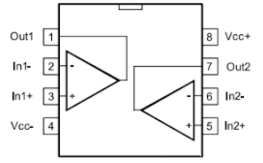
(IC Pins)
Leaving it floating is generally not recommended because the input pins can pick up noise, causing the output to saturate and potentially increasing power consumption.
What if both the non-inverting and inverting inputs are connected to ground? This puts the op-amp in an open-loop configuration, so its output may not be well controlled.
For a typical voltage-feedback op-amp, if permitted by the datasheet, a better approach is to configure the unused channel as a voltage follower: connect the output to the inverting input to create negative feedback, and connect the non-inverting input to GND.
However, the op-amp's input common-mode range and output swing must also be checked to ensure that this configuration is within the device's specifications.
Unused ADC channels should be handled according to the device datasheet.
Some devices recommend connecting unused ADC inputs to GND or another stable reference level to prevent the channel from picking up noise. However, directly connecting the input to ground should not be treated as a universal rule for all ADCs.
Therefore, unused ADC inputs should not simply be treated in the same way as digital GPIOs. Always check the manufacturer's recommended connection method before finalizing the schematic design.
IC datasheets often contain pins marked as NC, or "No Connect." These NC pins need to be examined carefully.
NC does not necessarily mean that the pin can be connected in any way. Some NC pins may have no internal connection and should simply be left floating. However, other pins marked as NC may have internal connections related to testing, reserved functions, or other circuits.
The handling method must strictly follow the datasheet.
For example, some datasheets specify "Must be left floating," while others specify "Must be tied to GND."
If you connect NC pins to ground without checking the datasheet, you could potentially cause unexpected behavior or interfere with internal test or reserved functions.
When dealing with unused IC pins, the most important principle is not simply whether a pin should be left floating or connected to ground. Instead, first identify the pin type and then follow the connection requirements specified in the datasheet.
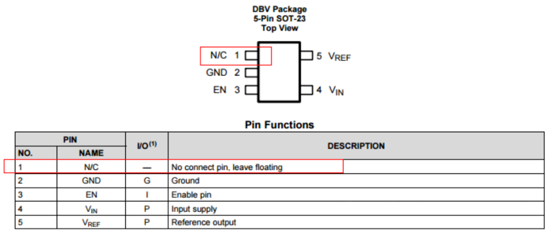
(DBV package)
Different types of GPIOs, analog inputs, op-amp channels, and NC pins may require completely different handling methods.
In simple terms:
A simple "Not Connected" label on a schematic may involve power consumption, noise, stability, and even device reliability. Do not rely on assumptions. Check the datasheet first, then decide how the pin should be connected.