


designs and builds a formula-type racecar each year to take to this competition
Competition Introduction with related photos:
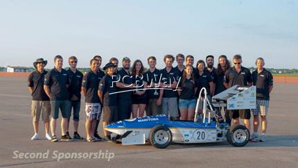
The competition I am preparing for is the SAE Collegiate Design Series. I'm a part of UMSAE, the University of Manitoba chapter of SAE International, a team which designs and builds a formula-type racecar each year to take to this competition. Here's a photo of us from our most recent competition in Lincoln, Nebraska. Unfortunately, I'm the fifth person from the left, with my face covered:
Project Introduction:
I am a member of UMSAE – the University of
Manitoba chapter of SAE International, and I work on the formula team, which
competes in the FSAE Collegiate Design Series. On my team, I am
responsible for the system which relays information to the driver. My design
consists of an electronic dashboard and an indicator module which will be
located in the steering wheel of our car. My project consists of two printed
circuit boards – one for the dashboard, and one for the steering wheel. I would
be very happy to have this first project manufactured for free, and I am also
very interested in the reduced manufacturing charge which students in
competitions can utilize.
A. Project Details
I will summarize the function of both PCBs:
Dashboard
? Gear position
? Shift timing
? Failure or damage to critical
systems
Indicator Module (IM)
? Coolant temperature
? Fuel level
? Acceleration
? Oil pressure
? Battery voltage
This driver interface is an iteration on last year's
driver interface. Last year, the entire driver interface module was located in
the dashboard. Our drivers complained that this made the dashboard too
cluttered. Therefore this year we decided to only provide basic, necessary
information via the dashboard, and move the less important information to the
steering wheel. Another problem which was encountered last year was that the
driver interface module was drawing too much current out of its power supply.
By splitting the driver interface into two separate modules, each with its own
power supply, we hope to alleviate this issue and improve the reliability of
our system.
- Comments(0)
- Likes(0)
 More by hughsonm
-
 my cycle racing project
The competition I am preparing for is the SAE Collegiate Design Series. I'm a part of UMSAE, the...
my cycle racing project
The competition I am preparing for is the SAE Collegiate Design Series. I'm a part of UMSAE, the...
-
 designs and builds a formula-type racecar each year to take to this competition
Competition Introduction with related photos: The competition I am preparing for is the SAE C...
designs and builds a formula-type racecar each year to take to this competition
Competition Introduction with related photos: The competition I am preparing for is the SAE C...


